
Head coller

a collier and head technology, applied in the field of head coolers, can solve the problems of hair loss in patients undergoing treatment with cytostatics (chemotherapy) or similar treatments, affecting the cooling effect of the scalp, and forming a gap between the heat exchange surface and the head,

Active Publication Date: 2012-02-16
BRAINCOOL
View PDF5 Cites 20 Cited by
  • Summary
  • Abstract
  • Description
  • Claims
  • Application Information

AI Technical Summary

Benefits of technology

"The present invention provides a head cooler for preventing hair loss during chemotherapy treatment. The device comprises a thermal exchange cap that is placed on the head and has a flow passage system for cooling the head. The thermal exchange cap can be adjusted to compensate for any discrepancies in shape and size between the inside surface of the cap and the head. The head cooler also has an outer insulating cover made of a heat insulating material, which encloses the thermal exchange cap and can be inflated with a cooling fluid. The cooling fluid flows through the flow passages in the cap and can be controlled by controlling the flow of air or gas. The invention also provides a complementary eyebrow cooler for added protection."

Problems solved by technology

A human being undergoing treatment with cytostatics (chemotherapy) or similar treatment often suffers from loss of hair.
If the head cooler is too large or too wide, a gap may be formed between the heat exchange surface and the head.
Then, the cooling of the scalp may be jeopardized, since the heat exchange surface is not held in contact with the scalp over the entire surface thereof.
As a consequence the cooling efficiency will be reduced in the area of the gap resulting in loss of hair.
A drawback with currently used head coolers is that the head cover is not easily adaptable to the size and / or shape of the patient's head and neck, which may result in a too low or an impaired cooling efficiency.
Another disadvantage is that the currently presented head coolers do not involve the cooling of the eyebrows or the region of the eyebrows.
Loss of the eyebrows is also considered to be a problem for patients undergoing treatments with cytostatics.

Method used


Image

  • Head coller
  • Head coller
  • Head coller

Examples


Embodiment Construction

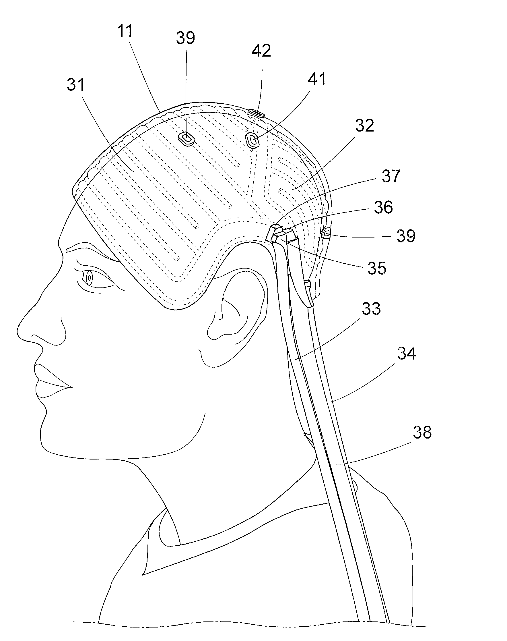
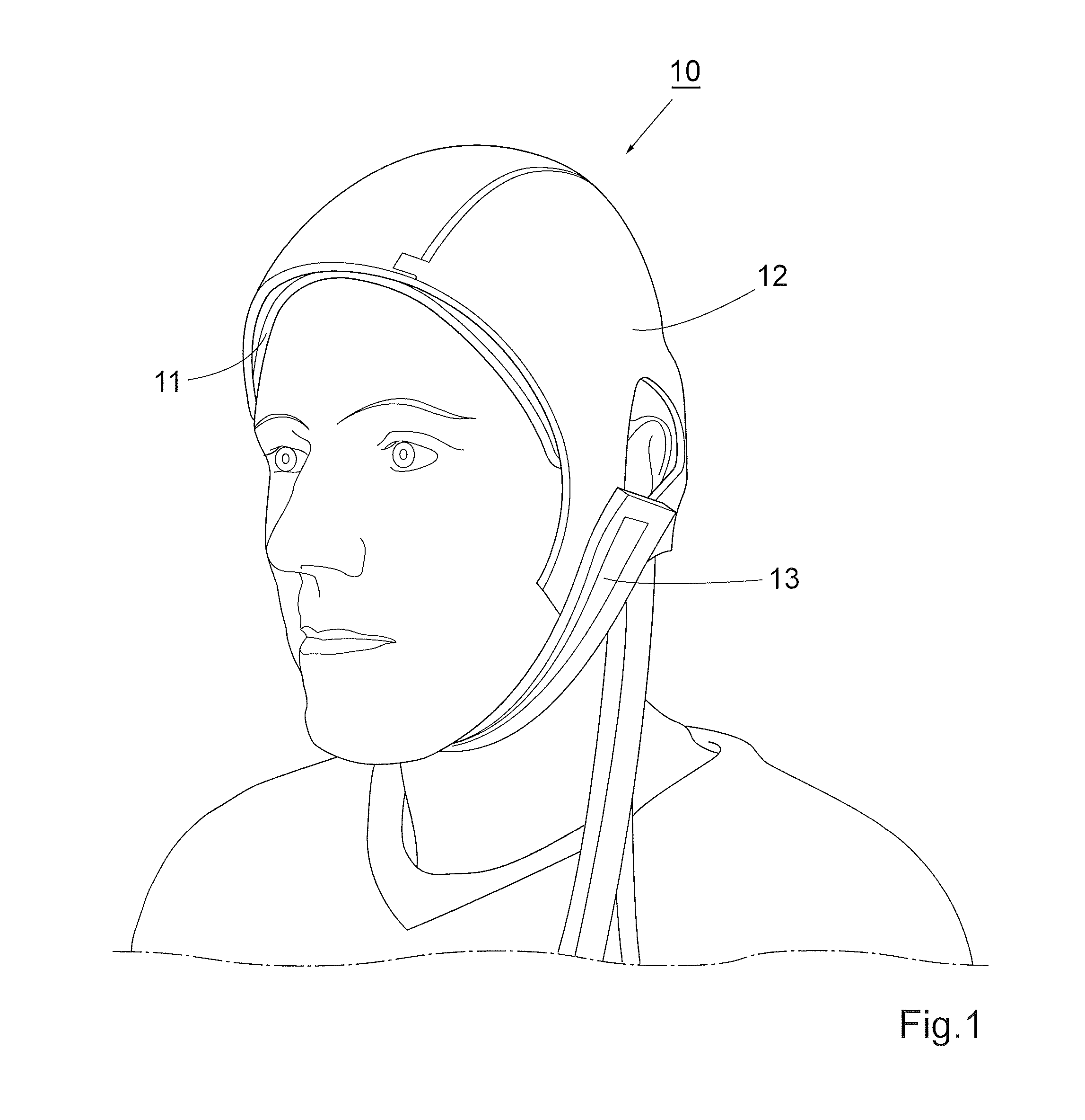
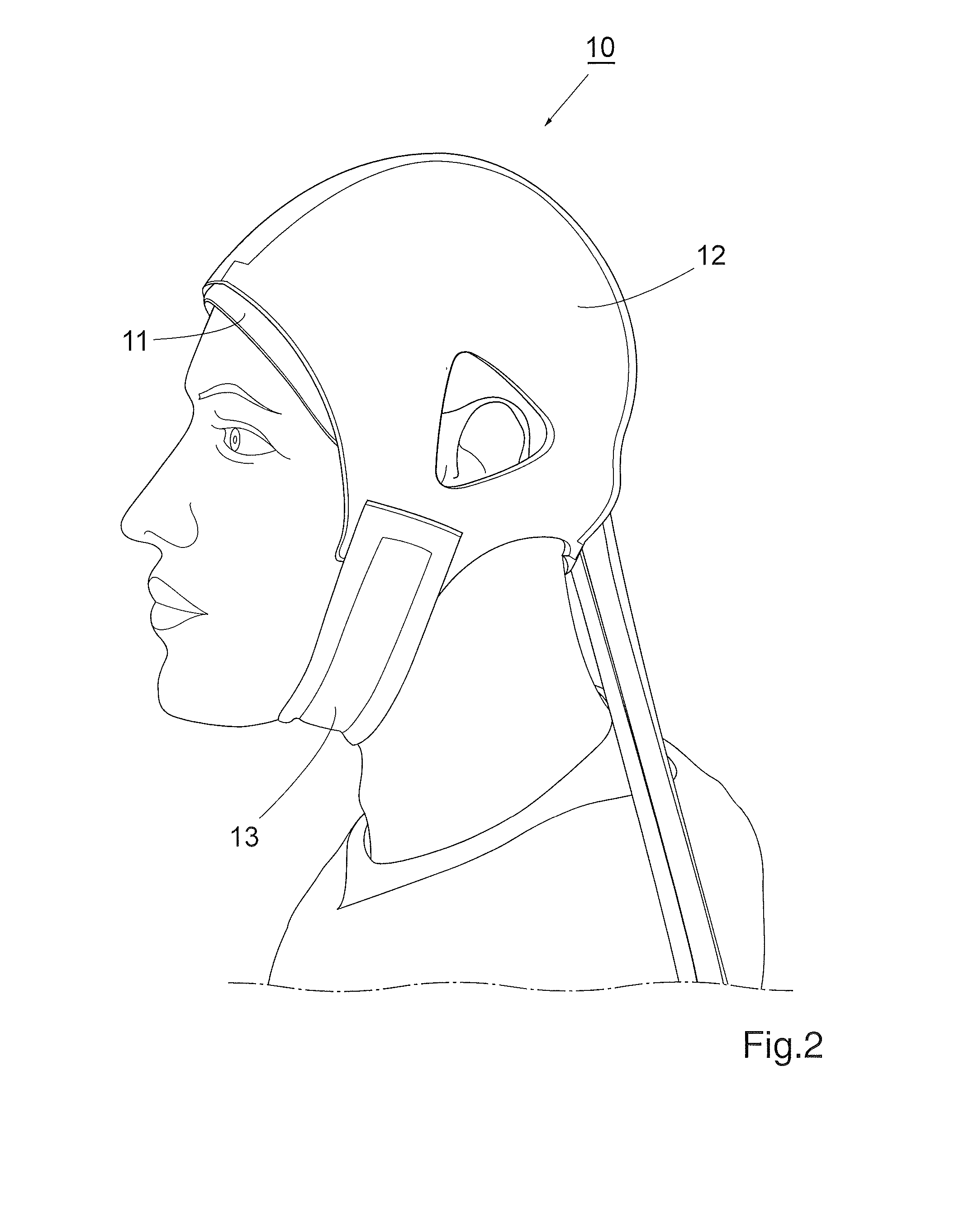
[0038]A head cooler 10 according to one embodiment of the invention comprises a thermal exchange cap 11 and an outer insulating cap 12, as shown in FIGS. 1 and 2. The outer insulating cover is fitted over the thermal exchange cap to stabilize the cap on the patient. The outer cover is made of a heat insulating and elastic material, e.g. neoprenes of the type used in diving suits, to heat insulate the thermal exchange cap against the surroundings.

[0039]A chinstrap 13 can improve the stabilization of the outer insulating cover. A first end of the strap is attached to the lower margin at one side of the outer cover and a second end of the strap, which is provided with a Velcro type fastener for adjustable and releasable connection, is attached at the other side of the outer cover.

[0040]FIGS. 3, 4 and 5 show the head cooler without the outer insulating cover. The thermal exchange cap 11 is made of a flexible and preferably elastic material, such as silicone rubber of medical grade, to f...


PUM


Abstract

A head cooler (10) comprises a thermal exchange cap (11) and an outer insulating cover (12) to be arranged on a patient's head. The cap (11) has a channel system (31, 32) for a cooling fluid forming an inside heat exchange surface to be applied on said head for cooling the head. The thermal exchange cap (11, 60) is adjustable and / or adaptable to compensate for a discrepancy in shape and size between the inside surface of the head cooler (10) and the head. The head cooler (10) may further comprise an eyebrow cooler (140) for cooling the area of the eyebrows. The head cooler (140) is used in medicine. A method for preventing hair loss of a patient is provided by arranging the head cooler (10) on the head of said patient.

Description

[0001]This application is a Divisional of U.S. Ser. No. 12 / 525,744, filed 4 Aug. 2009, which is a National Stage Application of PCT / EP2008 / 051890, filed 15 Feb. 2008, which claims benefit of Serial No. 0700374-2, filed 15 Feb. 2007 in Sweden and which applications are incorporated herein by reference. To the extent appropriate, a claim of priority is made to each of the above disclosed applications.TECHNICAL FIELD[0002]The present invention relates to a head cooler to be arranged at the head of a person undergoing treatment of cytostatics.BACKGROUND OF THE INVENTION[0003]A human being undergoing treatment with cytostatics (chemotherapy) or similar treatment often suffers from loss of hair. By maintaining, during the treatment, a low temperature on / at / of the hairy region, usually the scalp, such a loss can be eliminated or substantially reduced.[0004]A head cooler disclosed in U.S. Pat. No. 6,156,059 comprises a head cover to be placed over a human scalp for enclosing the patient's h...

Claims


Application Information

Patent Timeline
Patent Type & Authority Applications(United States)
IPC IPC(8): A61F7/10
CPCA61F7/10A61F2007/0004A61F2007/0287A61F2007/0056A61F2007/0247A61F2007/0008A61F7/02A61F7/00
Inventor STORMBY, JOHAN
Owner BRAINCOOL
Learn More