Interlock system for tubular running tools

a running tool and interlocking technology, applied in the direction of drilling casings, drilling pipes, borehole/well accessories, etc., can solve the problems of unsafe situations, conventional interlocking systems, and unsuitable for most casing installation operations

Inactive Publication Date: 2012-02-23
MATHERNE JR LEE J +2
View PDF4 Cites 10 Cited by
  • Summary
  • Abstract
  • Description
  • Claims
  • Application Information

AI Technical Summary

Problems solved by technology

This additional step in the casing running operations creates a problem for conventional interlock systems.
However, the spider slips must not be opened during this step because such slips are supporting the casing string in the wellbore.
This presents a potentially unsafe situation, and renders conventional interlock systems unsuitable for most casing installation operations utilizing an RT.

Method used


Image

  • Interlock system for tubular running tools
  • Interlock system for tubular running tools
  • Interlock system for tubular running tools

Examples


Embodiment Construction

[0028]While the present invention is described herein with reference to preferred embodiments, it will be understood by those skilled in the art that various changes may be made and equivalents may be substituted for elements thereof without departing from the scope of the invention. In addition, many modifications may be made to the present invention without departing from the scope of such invention. In addition, many modifications may be made to adapt a particular situation or material to the teachings of the invention without departing from the essential scope thereof. Therefore, it is intended that the present invention not be limited to the particular embodiments disclosed as the best mode contemplated for carrying out this invention, but that the invention will include all embodiments (and legal equivalents thereof) falling within the scope of this disclosure.

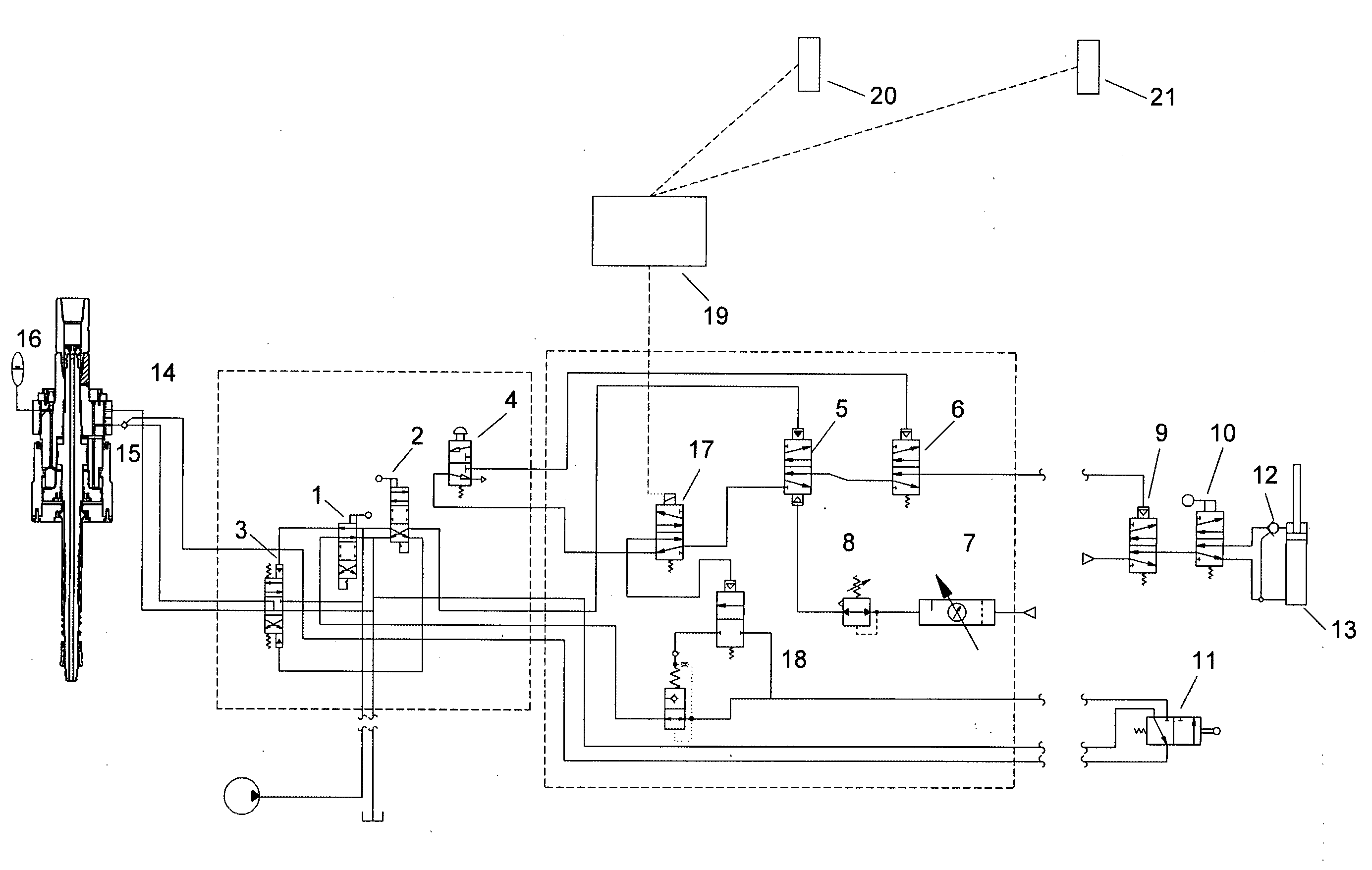
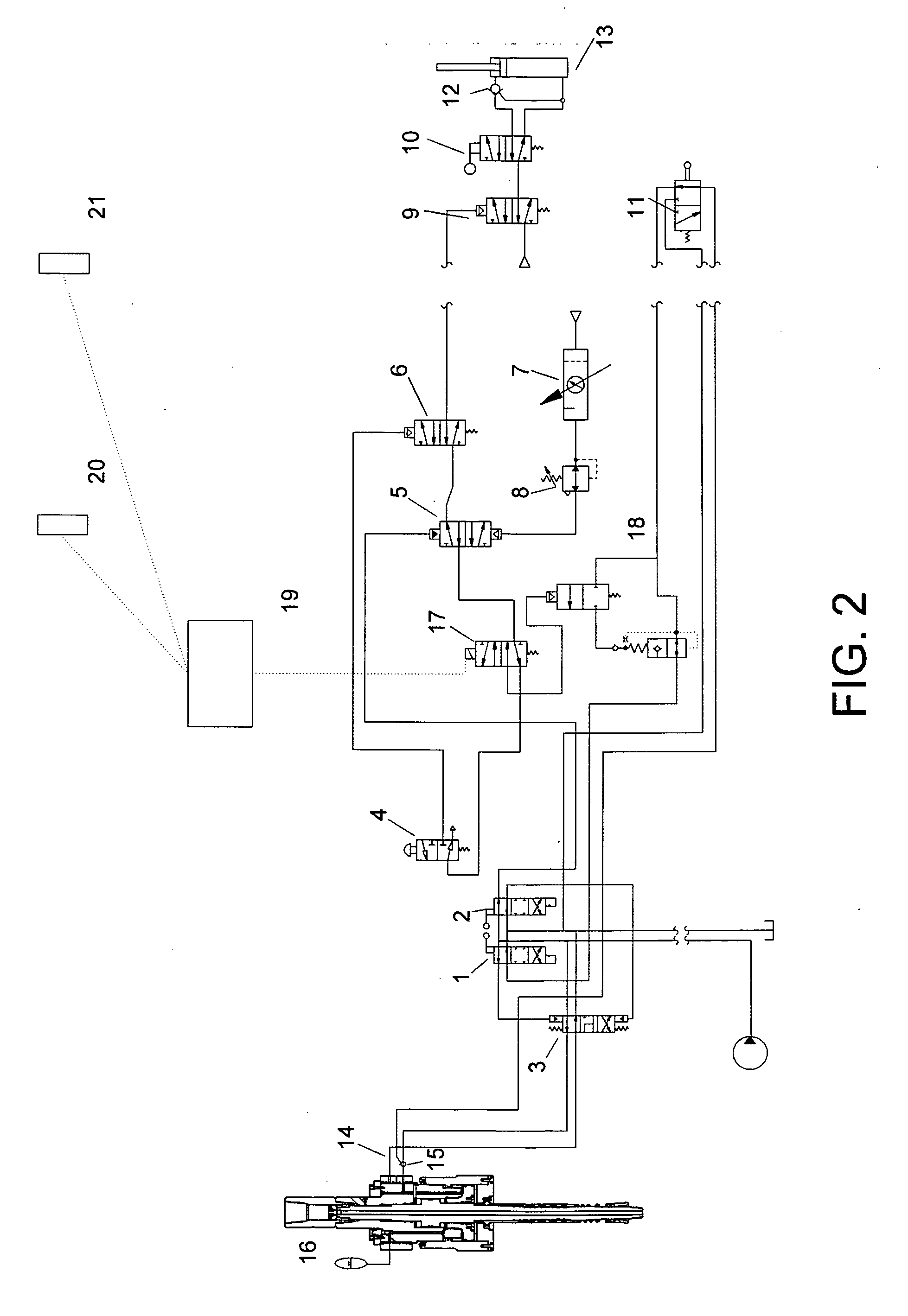
[0029]It is also to be observed that the present invention is described herein as employing pneumatic and hydraulic ac...


PUM


Abstract

An interlock system for use with casing running tools including, without limitation, casing running tools utilized with rig top drive systems. A pressure circuit is in communication with casing running tool slips and spider assembly slips. The pressure circuit controls the supply of pressure to: (1) release the spider slips only when the casing running tool slips are engaged and supporting the entire pipe string; and (2) release the casing running tool slips only when the spider slips are engaged and supporting the entire pipe string.

Description

CROSS REFERENCES TO RELATED APPLICATIONS[0001]THIS APPLICATION CLAIMS THE BENEFIT OF U.S. PROVISIONAL PATENT APPLICATION SER. NO. 61 / 373,633, FILED AUG. 13, 2010, WHICH IS INCORPORATED HEREIN BY REFERENCE FOR ALL PURPOSES.FEDERALLY SPONSORED RESEARCH[0002]Not ApplicableBACKGROUND OF INVENTION[0003]1. Field of Invention[0004]The present invention pertains to an interlock system for use with tubular running systems. More particularly, the present invention pertains to an interlock system for use with casing running tools including, without limitation, casing running tools utilized with rig top drive systems.[0005]2. Description of Related Art[0006]Once a well bore has been drilled to a desired depth, large diameter pipe called casing is frequently installed in said well bore and cemented in place. Such casing is usually inserted into a well in a number of separate sections of substantially equal length called “joints.” The joints are typically screwed together or otherwise joined end-...

Claims


Application Information

Patent Timeline
Patent Type & Authority Applications(United States)
IPC IPC(8): E21B19/16
CPCE21B19/10
Inventor MATHERNE, JR., LEE J.HENDERSON, KRISROBICHAUX, LEE M.
Owner MATHERNE JR LEE J
Why Eureka
Try Eureka