Gripping Tool

a tool and tool body technology, applied in the field of sliding, can solve the problems that the power tong method does not support other beneficial functions, rotation, pushing or fluid, and simultaneously supports other beneficial functions

Active Publication Date: 2008-09-04
NOETIC TECH INC
View PDF45 Cites 62 Cited by
  • Summary
  • Abstract
  • Description
  • Claims
  • Application Information

AI Technical Summary

Problems solved by technology

But this power tong method does not simultaneously support other beneficial functions such as rotating, pushing or fluid filling, after a pipe segment is added to or removed from the string, and while the string is being lowered or raised in the well bore.

Method used


Image

  • Gripping Tool
  • Gripping Tool
  • Gripping Tool

Examples


Embodiment Construction

General Principles

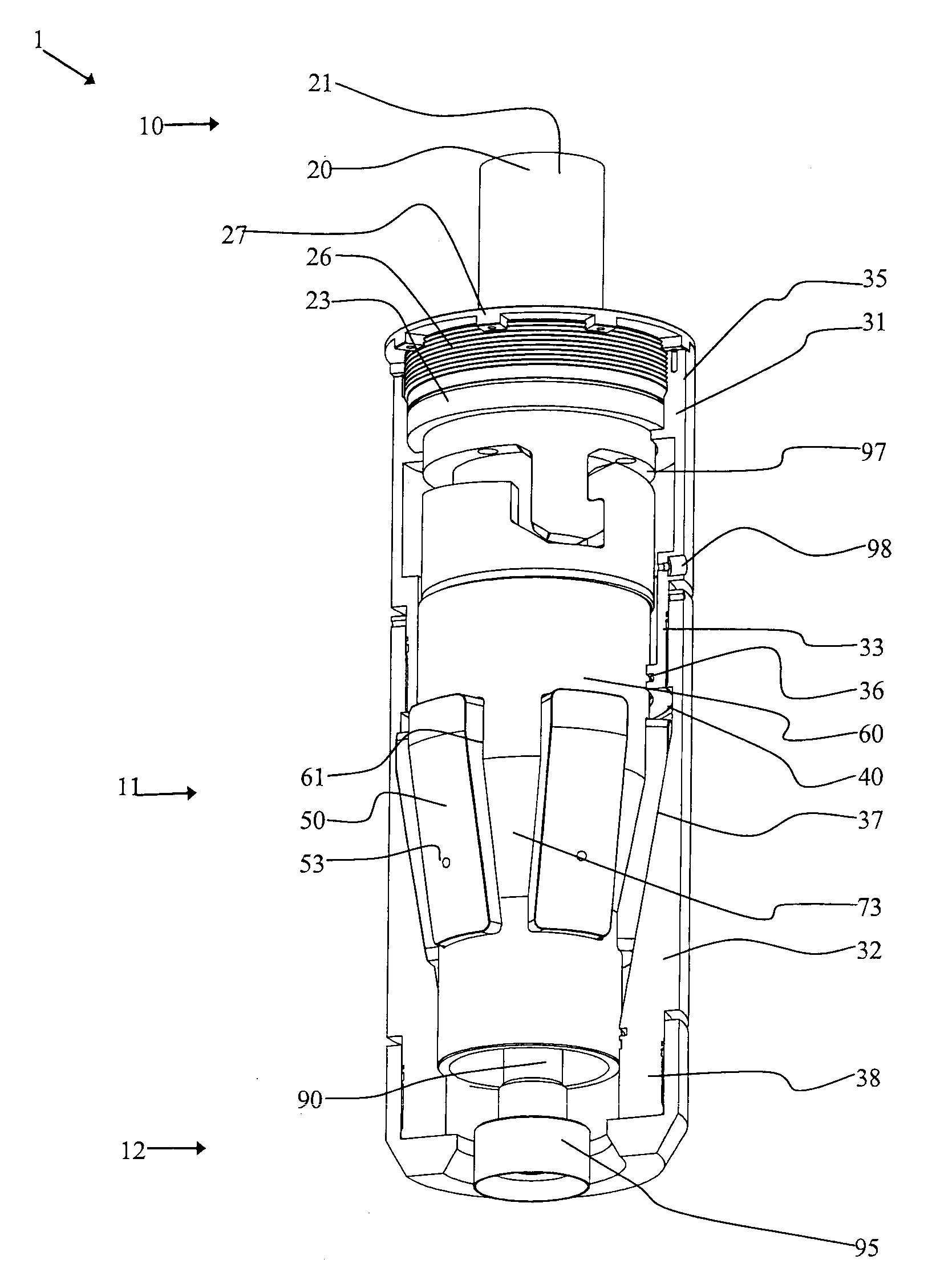
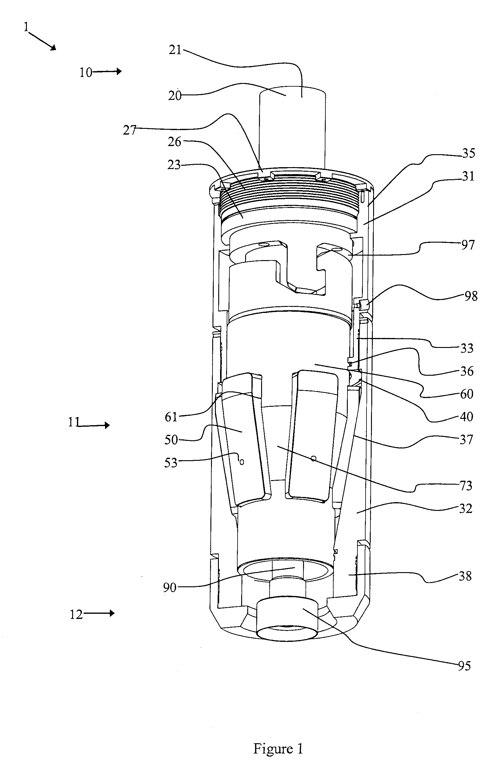
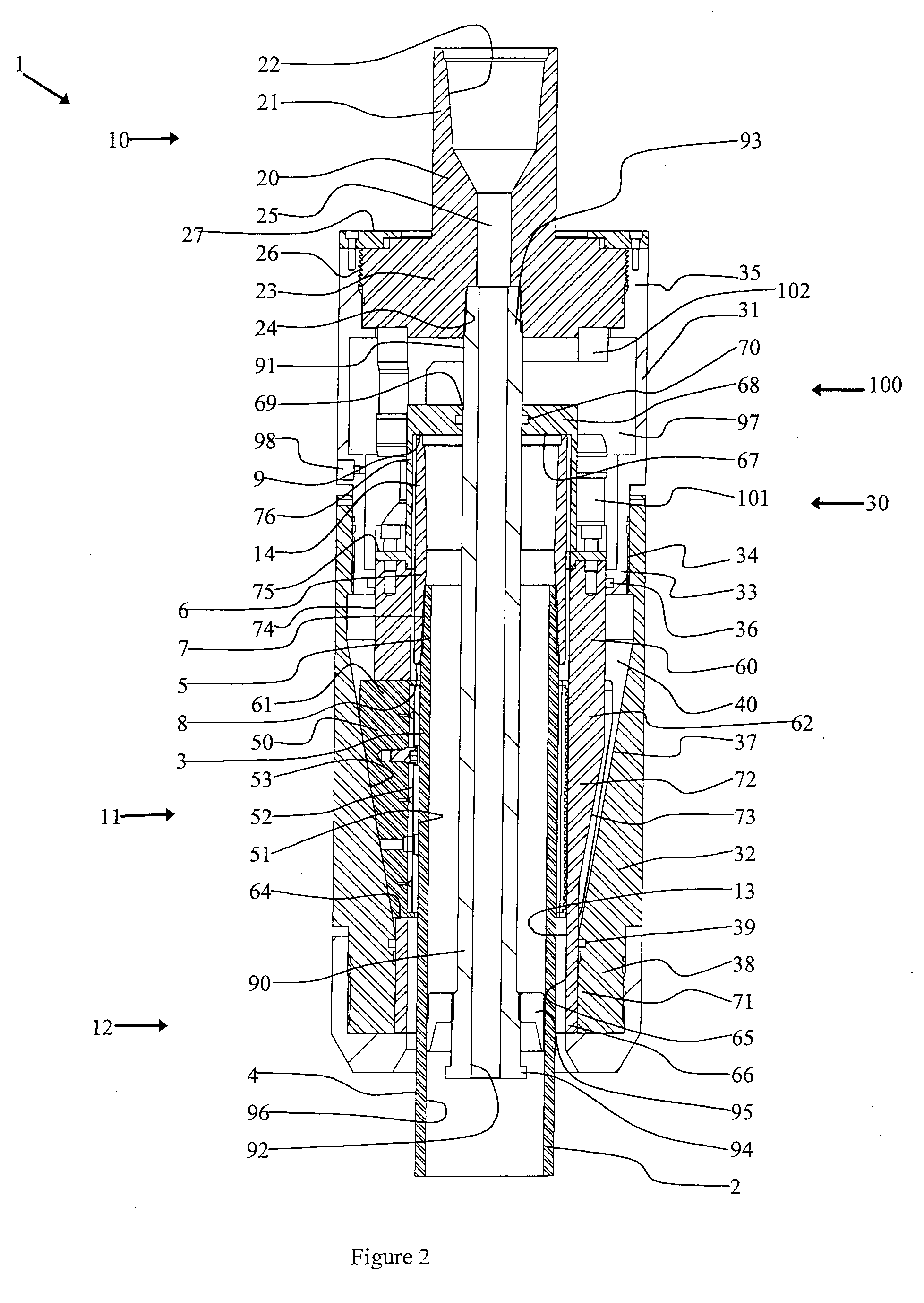
[0054]The tool is comprised of three main interacting components or assemblies: 1) a body assembly, 2) a gripping assembly carried by the body assembly, and 3) a linkage acting between the body assembly and gripping assembly. The body assembly generally provides structural association of the tool components and includes a load adaptor by which load from a drive head or reaction frame is transferred into or out of the remainder of the body assembly or the main body. The gripping assembly, has a grip surface, is carried by the main body of the body assembly and is provided with means to move the grip surface from a retracted to an engaged position in response to relative axial movement, or stroke, to radially and fractionally engage the grip surface with a work piece. The gripping assembly thus acts as an axial load or stroke activated grip element. The linkage acting between the body assembly and gripping assembly is adapted to link relative rotation between the loa...


PUM


Abstract

A gripping tool includes a body assembly and gripping assembly with a grip surface adapted to move from a retracted position to an engaged position to radially engage a work piece in response to relative axial displacement. A linkage is provided to act between the body assembly and the gripping assembly which, upon relative rotation in at least one direction, of the body relative to the grip surface results in relative axial displacement of the grip surface to activate the gripping elements. This tool was developed for use on drilling and service rigs having top drives, and supports rapid engagement and release, hoisting, pushing, and rotating.

Description

FIELD OF THE INVENTION[0001]This invention relates generally to applications where tubulars and tubular strings must be gripped, handled and hoisted with a tool connected to a drive head or reaction frame to enable the transfer of both axial and torsional loads into or from the tubular segment being gripped. In the field of earth drilling, well construction and well servicing with drilling and service rigs this invention relates to slips, and more specifically, on rigs employing top drives, applies to a tubular running tool that attaches to the top drive for gripping the proximal segment of tubular strings being assembled into, deployed in or removed from the well bore. This tubular running tool supports various functions necessary or beneficial to these operations including rapid engagement and release, hoisting, pushing, rotating and flow of pressurized fluid into and out of the tubular string.BACKGROUND OF THE INVENTION[0002]Until recently, power tongs were the established method...

Claims


Application Information

Patent Timeline
Patent Type & Authority Applications(United States)
IPC IPC(8): B25B7/02
CPCE21B19/06E21B23/006E21B23/00E21B19/16E21B19/07E21B3/022B25B13/50
Inventor SLACK, MAURICE WILLIAM
Owner NOETIC TECH INC
Why Eureka
Try Eureka