Double-frame magnetic suspension control moment gyro

A technology for controlling torque gyroscopes and magnetic levitation, which is applied to the guidance devices of space navigation vehicles, etc., can solve the problems of reducing the service life and reliability of the system by the rotor speed, increasing the weight and volume of the control torque gyroscope, and increasing the power consumption of the system, so as to improve the use of the system. Effects of life and control accuracy, reduction in size and weight, and improved torque resolution

Inactive Publication Date: 2008-07-16
BEIHANG UNIV
View PDF0 Cites 53 Cited by
  • Summary
  • Abstract
  • Description
  • Claims
  • Application Information

AI Technical Summary

Problems solved by technology

As the supporting part of the flywheel rotor, the existing double-frame control moment gyroscope is supported by mechanical bearings, which fundamentally limits the increase of the rotor speed, reduces the service life and reliability of the system, and increases the power consumption, vibration and The noise is high and the control accuracy is low. In order to make the control moment gyro output the required angular momentum, the weight and volume of the control moment gyro have to be increased
Therefore, the main disadvantages of the existing dual-frame control moment gyroscopes are large volume and weight, low control accuracy, poor reliability, and relatively short service life.

Method used


Image

  • Double-frame magnetic suspension control moment gyro
  • Double-frame magnetic suspension control moment gyro
  • Double-frame magnetic suspension control moment gyro

Examples


Embodiment Construction

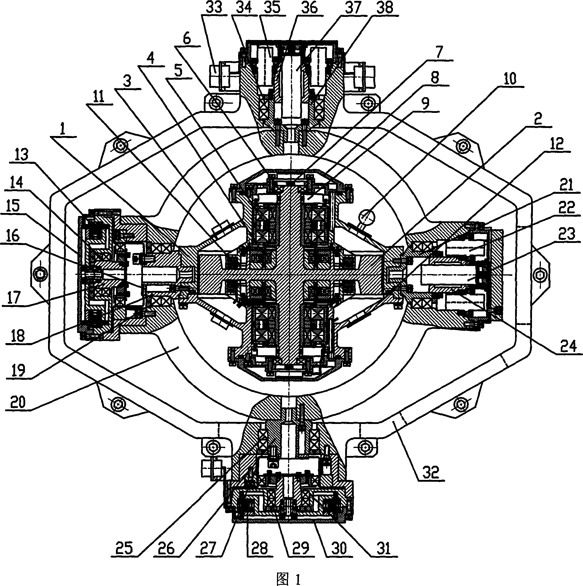
[0028] As shown in Figure 1, the high-speed motor 4 that the present invention implements needs to be used in pairs and is in the middle part of flywheel rotating shaft 2, and axial hybrid magnetic levitation magnetic bearing 11 needs to be used in pairs and is in the outside of high-speed motor 4, radial hybrid magnetic bearing 5 Need to be used in pairs and located on the upper and lower sides of the high-speed motor 4, the stator part of the high-speed motor 4, the static part of the radial hybrid magnetic bearing 5 and the axial hybrid magnetic levitation magnetic bearing 11 are respectively connected with the upper gyro room 1 and the lower gyro room 12 , the upper gyro room 1 and the lower gyro room 12 are connected with the upper and lower end covers 8 respectively; the rotor part of the high-speed motor 4 and the rotating part of the radial hybrid magnetic bearing 5 are connected with the flywheel shaft 2; the upper end of the radial hybrid magnetic bearing 5 is The rad...


PUM


Abstract

The invention relates to a magnetic suspension controlled moment gyro with double frames, essentially consisting of a flywheel, an inner frame system and an outer frame system. The flywheel is arranged in the middle of the magnetic suspension controlled moment gyro with the double frames and essentially comprises a rotary shaft, a radial mixed magnetic bearing, an axial magnetic bearing, a radial displacement sensor, an axial displacement sensor, a high-speed motor and a gyro room; the inner frame system and the outer frame system essentially comprise the frames, a mechanical bearing, a moment motor, a reducer, an angle position sensor, a conductive slip ring a control system; the inner frame system is connected with a shaft hole on one end of the gyro room through the reducer and at the same time the conductive slip ring and the angle position sensor are connected with the shaft hole on the other end of the gyro room; the outer frame system is connected with a shaft hole on one end of the inner frame through the reducer and at the same time the conductive slip ring and the angle position sensor are connected with the shaft hole on the other end of the inner frame. The invention reduces noise, size and weight of the system through the mixed magnetic bearing, and eliminates bearing friction, and thus prolongs life span and promotes control accuracy of the controlled moment gyro.

Description

technical field [0001] The invention relates to a double-frame magnetic levitation control moment gyroscope, which can be used as an actuator for attitude control systems of large-scale spacecraft such as spacecraft and space stations that operate for a long time or require large maneuverability and quick response. Background technique [0002] The control moment gyro is a kind of inertial actuator applied to the spacecraft. It is mainly composed of a flywheel and a frame system. The direction of the angular momentum of the flywheel is controlled by the frame servo system, so that the gyro torque is output to control the attitude of the spacecraft. The attitude control actuators of spacecraft requiring large maneuverability and quick response and large spacecraft such as space stations require large output torque, long life, high reliability, fast response, high precision, small size, light weight, and low power consumption. This requires that the rotational speed of the fly...

Claims


Application Information

Patent Timeline
Patent Type & Authority Applications(China)
IPC IPC(8): B64G1/28
Inventor 韩邦成房建成孙津济李海涛魏彤刘珠荣
Owner BEIHANG UNIV
Why Eureka
Try Eureka