Applicator tip for liquid applicator device

a technology of liquid applicator and applicator tip, which is applied in the field of liquid dispenser, can solve the problems of deficient methods of affixing the fiber tip, other problems persist,

Inactive Publication Date: 2003-11-04
BALLOT RICHARD W +1
View PDF15 Cites 56 Cited by
  • Summary
  • Abstract
  • Description
  • Claims
  • Application Information

AI Technical Summary

Problems solved by technology

Although the aforementioned U.S. Patents solved many of the problems of the prior art, other problems persisted in the use of liquid applicator devices of this type.
A major problem in the design and the utilization of liquid applicator devices of this type involves the retention of the fiber tip in the hollow cylindrical closure of the outer subassembly.
These methods of affixing the fiber tip are deficient in that they tend to loosen and detach from the liquid applicator.

Method used


Image

  • Applicator tip for liquid applicator device
  • Applicator tip for liquid applicator device
  • Applicator tip for liquid applicator device

Examples


first embodiment

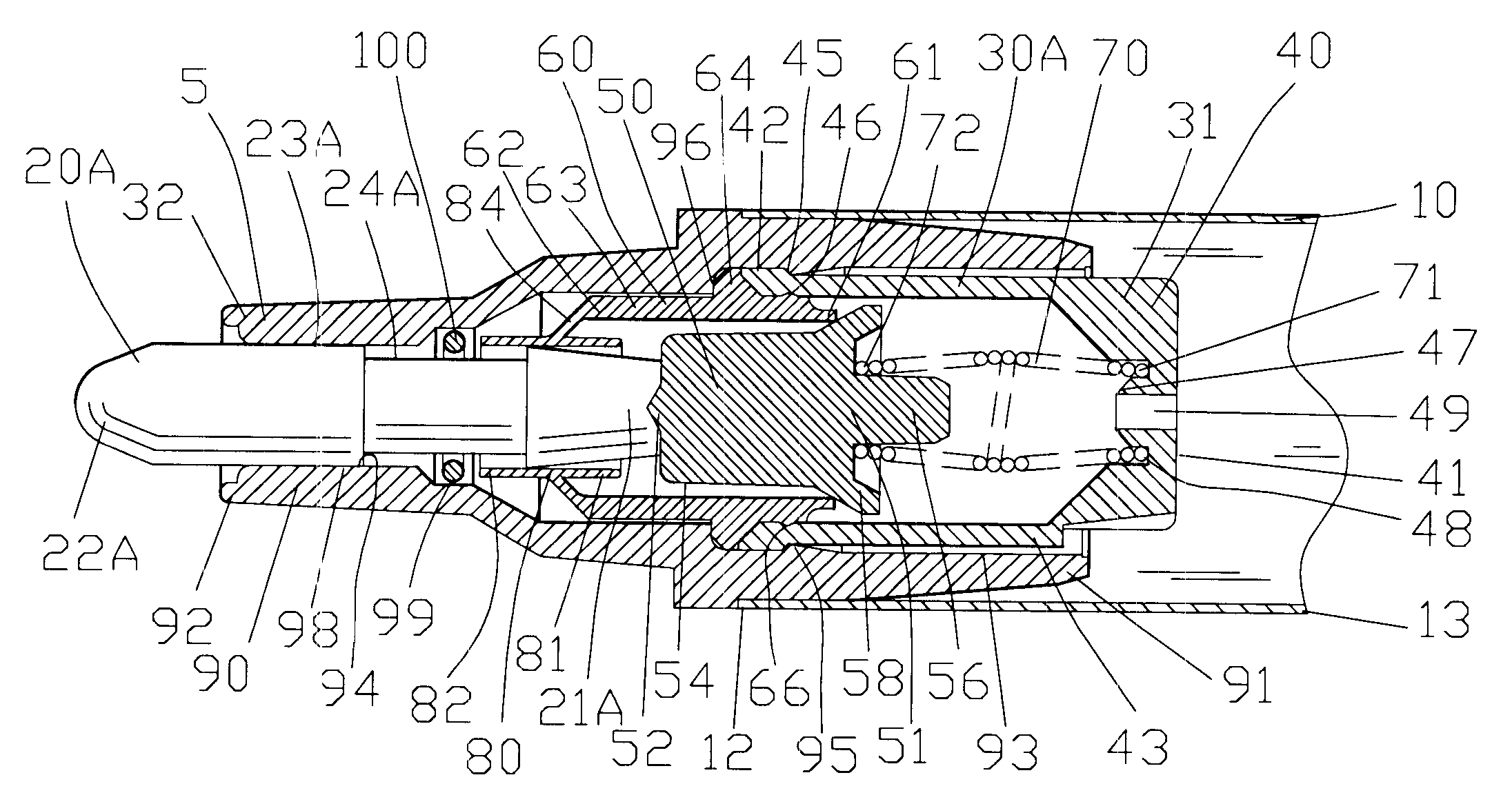
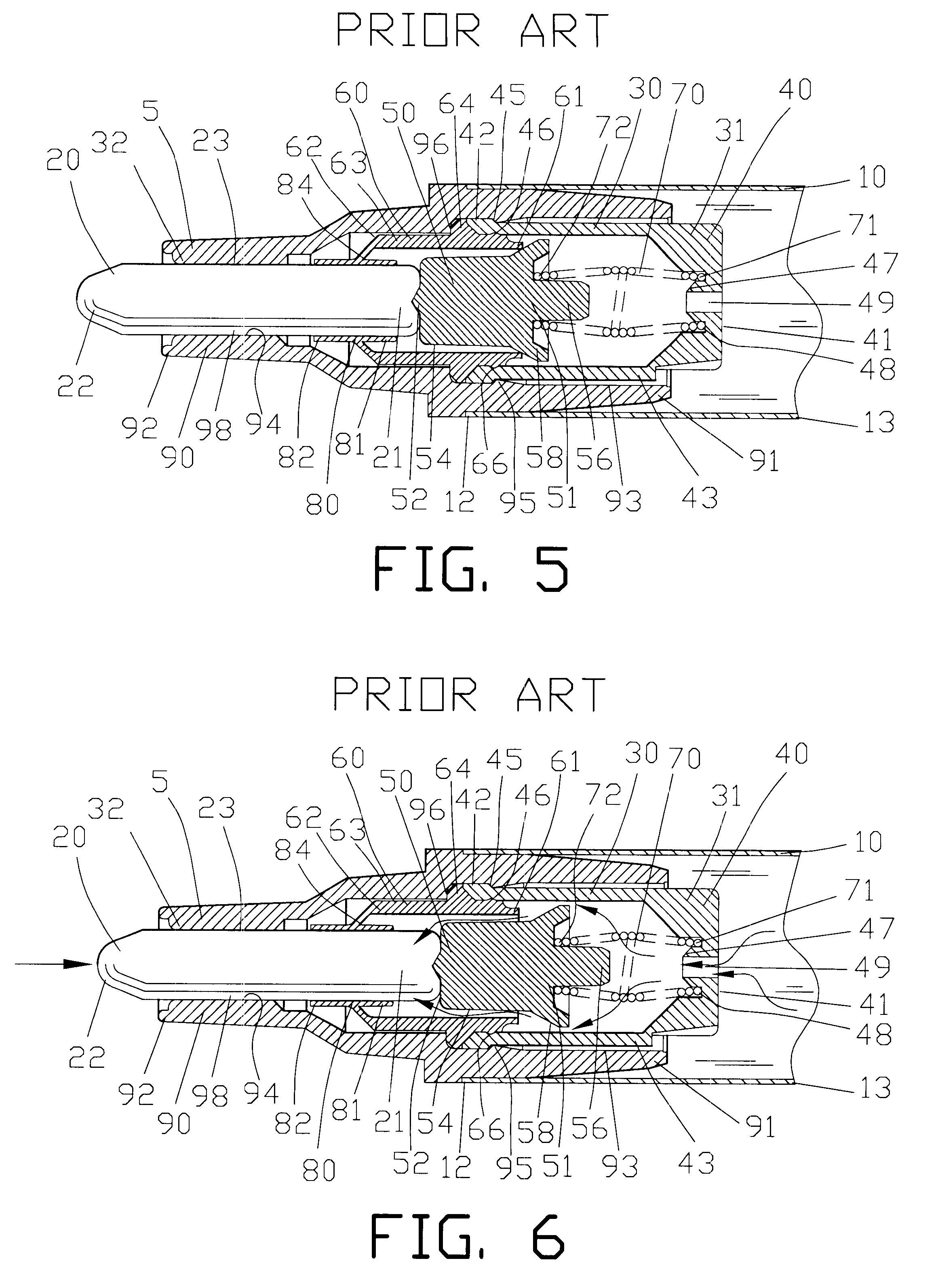
FIG. 15 is a view similar to FIG. 14 of the applicator tip 20A of the present invention within the liquid dispensing mechanism 30 in an open position. The position of the applicator tip 20A is shown in phantom when the liquid dispensing mechanism 30 is in the closed position. The applicator tip 20A extends between the inner end 21A and the outer end 22A with the annular recess 24A located therebetween. The annular recess 24A extends between the inner shoulder 26A and the outer shoulder 28A. In the present invention, the annular recess 24A extends along approximately one-quarter of a cylindrical length of the applicator tip 20A.

FIG. 16 is a view similar to FIG. 15 illustrating a second embodiment of an applicator tip 20B of the present invention within the liquid dispensing mechanism 30 in an open position. The position of the applicator tip 20B is shown in phantom when the liquid dispensing mechanism 30 is in the closed position. The applicator tip 20B extends between the inner end ...

third embodiment

FIGS. 17-19 are magnified views of the applicator tip 20C of present invention. The applicator tip 20C extends between the inner end 21C and the outer end 22C and defines a cylindrical diameter 23C. The applicator tip 20C includes an annular recess 24C located intermediate the inner end 21C and the outer end 22C of the applicator tip 20C. The annular recess 24C defines a recess diameter 25C extending between an inner shoulder 26C and an outer shoulder 28C. The cylindrical diameter 23C of the applicator tip 20C is greater than the recess diameter 25C of the annular recess 24C.

In this third embodiment of the invention, the applicator tip 20C comprises a sheath 120C having an internal passage 122C. Preferably, the sheath 120C is formed from a rigid or semi-rigid material such as a suitable polymeric material. The inner end 21C of the applicator tip 20C includes a plurality of voids 29C defined in the sheath 120C. The plurality of voids 29C facilitate the flow of applicator liquid 8 to ...

fourth embodiment

FIGS. 23 and 24 are views of an applicator tip 20D of the present invention. The applicator tip 20D extends between the inner end 21D and the outer end 22D and defines a cylindrical diameter 23D. The applicator tip 20D includes an annular recess 24D located intermediate the inner end 21D and the outer end 22D of the applicator tip 20D. The annular recess 24D defines a recess diameter 25D extending between an inner shoulder 26D and an outer shoulder 28D. The cylindrical diameter 23D of the applicator tip 20D is greater than the recess diameter 25D of the annular recess 24D.

In this fourth embodiment of the invention, the applicator tip 20D comprises a sheath 120D having an internal passage 122D. Preferably, the sheath 120D is formed from a rigid or a semi-rigid material such as a suitable polymeric material. The inner end 21D of the applicator tip 20D includes a plurality of voids 29D defined in the sheath 120D. The plurality of voids 29D facilitate the flow of applicator liquid 8 to ...


PUM


Abstract

A liquid applicator device comprising an applicator liquid container and a liquid dispensing mechanism. The device has a valve element movable disposed between an open position and a closed position for controlling the flow of the applicator liquid from the container. The liquid dispensing mechanism has a hollow cylindrical portion for supporting an applicator tip. The inner end of the applicator tip communicates with the valve element. An axial displacement of the applicator tip moves the valve element into the open position for enabling the applicator liquid to migrate through the applicator tip for applying the liquid to a surface. The improvement comprises a recess cooperating with a retainer for preventing the removal of the applicator tip from the liquid applicator device.

Description

1. Field of the InventionThis invention relates to the dispensing of liquids and more particularly, this invention relates to an improved applicator device for marking, writing or dispensing a liquid on a surface.2. Background of the InventionVarious types of liquid applicator devices have been devised for dispensing a liquid. Some of these liquid applicator devices were used for dispensing an applicator liquid for writing with ink, dye or paint. Among such devices were fountain pens, ball point pens, felt tip pens as well as other types of liquid applicator devices and the like.These liquid applicator devices of the prior art have receiving wide acceptance due in great measure to the convenience of the device. Furthermore, these liquid applicator devices of the prior art had the ability to retain a large quantity of applicator liquid and the ability to supply additional applicator liquid from a liquid container to an applicator tip at the discretion of the user. In addition, the li...

Claims


Application Information

Patent Timeline
Patent Type & Authority Patents(United States)
IPC IPC(8): B43K5/18B43K5/00A45D34/04B05C17/00
CPCA45D34/042B43K5/1845B05C17/002
Inventor BALLOT, RICHARD W.BALLOT, STEPHAN M.
Owner BALLOT RICHARD W
Why Eureka
Try Eureka