Coupling for a surgical rotary drive hand piece

a rotary drive and hand piece technology, applied in the field of coupling for surgical rotary drive hand pieces, can solve the problem of redundant manual operation of locking mechanisms

Inactive Publication Date: 2006-03-16
AESCULAP AG
View PDF27 Cites 58 Cited by
  • Summary
  • Abstract
  • Description
  • Claims
  • Application Information

AI Technical Summary

Benefits of technology

[0006] In accordance with the invention, this object is achieved in the case of a coupling of the type described hereinabove in that a driver having at least one contact surface on the side thereof facing the tool and which rotates with the sleeve and is axially displaceable with respect thereto is arranged in the sleeve-shaped seating for the purposes of forming an interlocking rotary drive means, in that the driver is displaceable by the effect of a spring into a pushed-out position in which the locking body or bodies rest thereon and are thus held in their release position, in

Problems solved by technology

This could of course be effected manually, but is preferably achieved automatically b

Method used


Image

  • Coupling for a surgical rotary drive hand piece
  • Coupling for a surgical rotary drive hand piece
  • Coupling for a surgical rotary drive hand piece

Examples


Embodiment Construction

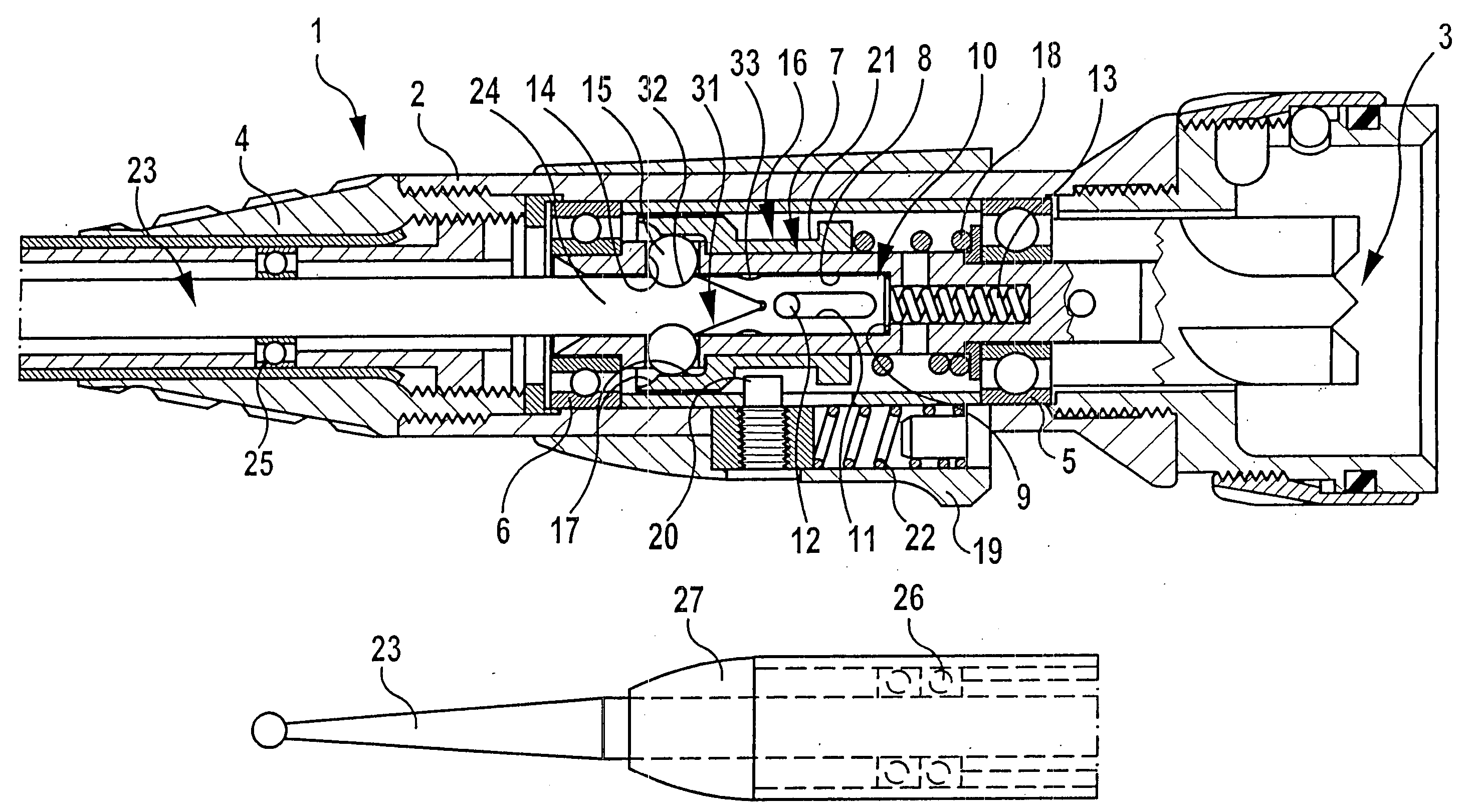
[0044] The hand piece 1 illustrated in the drawing comprises a cylindrical housing 2 having a connecting unit 3 on the rear face thereof and a conically tapering pointed part 4 at the opposite end thereof. With the aid of the connecting unit 3, the housing 2 is attached in a manner that is not apparent from the drawing to a drive means, for example, to an electric motor arranged in a housing.

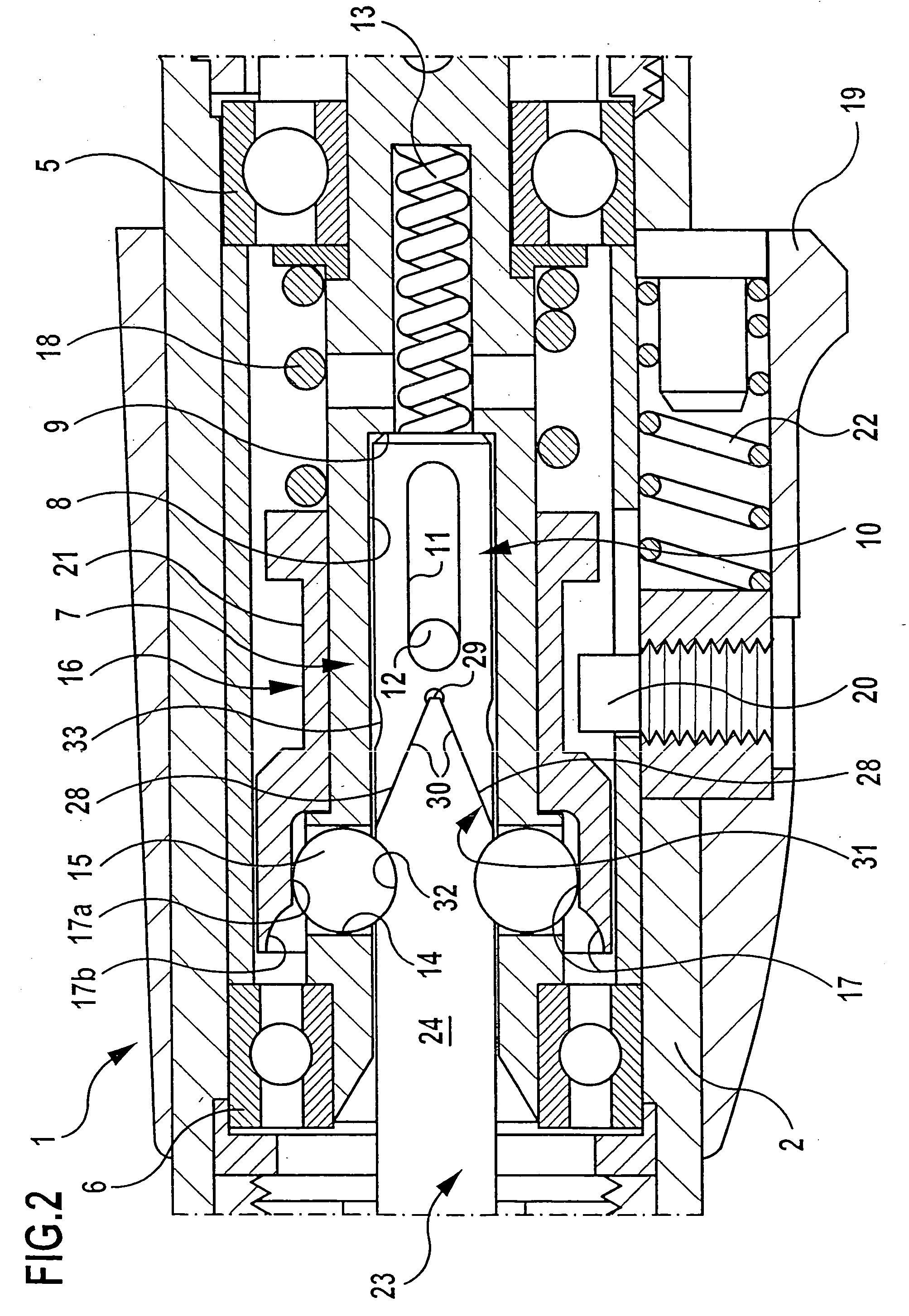
[0045] A cylindrical seating 7 in the form of a seating sleeve 7 that is open towards the front end of the hand piece 1 is mounted in the interior of the cylindrical housing 2 by means of two ball bearings 5, 6, the end of said seating sleeve facing the connecting unit 3 being connectible in mutually non-rotatable manner and in a manner that is not apparent from the drawing to the rotary drive of the motor attached to the connecting unit 3. The seating 7 has a cylindrical interior 8 which is open towards the pointed part 4 and is closed at the opposite end thereof by a base 9. A driver 10 is in...


PUM

PropertyMeasurementUnit
Fractionaaaaaaaaaa
Angleaaaaaaaaaa
Angleaaaaaaaaaa

Abstract

In order to simplify the insertion of the tool in the case of a coupling for a surgical rotary drive hand piece including a tool which is mounted in the hand piece and driven thereby in rotary manner and incorporating a sleeve-shaped, rotary driven seating in the hand piece into which a shank of the tool is adapted to be inserted so as to form an interlocking rotary drive means, and including at least one locking body which is adapted to be inserted radially into the interior of the seating and which, in an inserted locking position, engages in a recess in the shank and thereby secures it from axial displacement, whereas, in a radially withdrawn position, it leaves the recess and thus enables an axial displacement of the shank in the seating, it is proposed that a driver having at least one contact surface on the side thereof facing the tool and which rotates with the sleeve and is axially displaceable with respect thereto be arranged in the sleeve-shaped seating for the purposes of forming an interlocking rotary drive means, in that the driver is displaceable by the effect of a spring into a pushed-out position in which the locking body or bodies rest thereon and are thus held in their release position, in that the driver is displaceable by means of the shank of the tool resting thereon against the effect of the spring into a pushed-in position in which the locking body or bodies enter the locking position and can secure the shank of the tool from axial displacement, and in that the shank of the tool in the pushed-in position thereof secured from axial displacement by the locking body or bodies pushes the driver against the effect of the spring into the seating in such a manner that its contact surfaces rest against the contact surfaces of the tool so as to form a rotary drive means.

Description

[0001] This application is a continuation of international application number PCT / EP2004 / 000853 filed on Jan. 30, 2004. The present disclosure relates to the subject matter disclosed in international application PCT / EP2004 / 000853 of Jan. 30, 2004 and German application number 103 11 455.6 of Mar. 15, 2003, which are incorporated herein by reference in their entirety and for all purposes.BACKGROUND OF THE INVENTION [0002] The invention relates to a coupling for a surgical rotary drive hand piece including a tool which is mounted in the hand piece and driven thereby in rotary manner and incorporating a sleeve-shaped, rotary driven seating in the hand piece into which a shank of the tool is adapted to be inserted so as to form an interlocking rotary drive means, and including at least one locking body which is adapted to be inserted radially into the interior of the seating and which, in an inserted locking position, engages in a recess in the shank and thereby secures it from axial di...

Claims


Application Information

Patent Timeline
IPC IPC(8): B67B7/00A61B17/00A61B17/16A61C1/14B23B31/00
CPCA61B17/162B23B31/008A61C1/142A61B2017/0046
Inventor BLUST, EDGARMUELLER, THOMAS
Owner AESCULAP AG
Why Eureka
Try Eureka