Combined multi-coupler for top drive

a multi-coupler and top drive technology, applied in the direction of drilling pipes, rotary drilling, borehole/well accessories, etc., can solve the problems of time-consuming and dangerous process of changing tools, and require personnel to work at heights

Active Publication Date: 2017-03-09
WEATHERFORD TECH HLDG LLC
View PDF4 Cites 60 Cited by
  • Summary
  • Abstract
  • Description
  • Claims
  • Application Information

AI Technical Summary

Problems solved by technology

The process of changing tools is very time consuming and dangerous requiring personnel to work at heights.

Method used


Image

  • Combined multi-coupler for top drive
  • Combined multi-coupler for top drive
  • Combined multi-coupler for top drive

Examples


Embodiment Construction

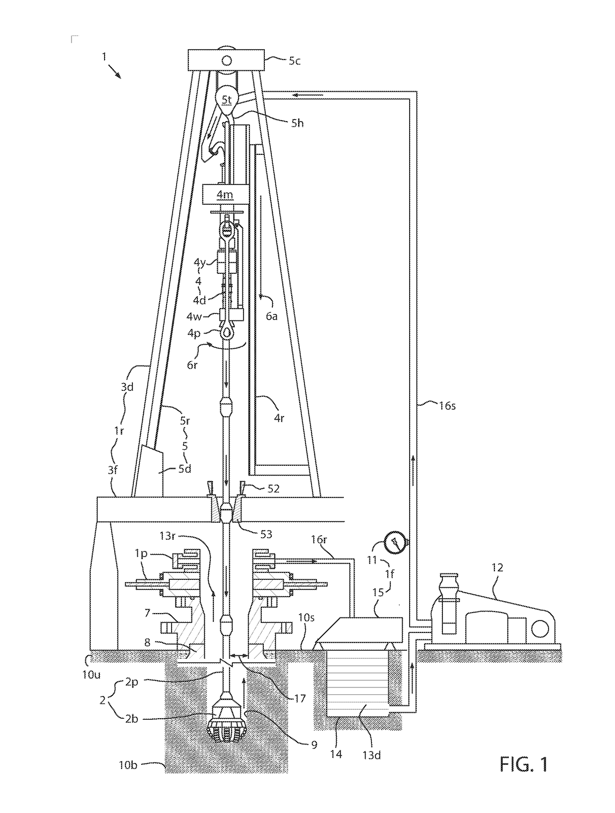
[0032]FIG. 1 illustrates a drilling system 1 in a drilling mode, according to one embodiment of the present disclosure. The drilling system 1 may include a drilling rig 1r, a fluid handling system 1f, a pressure control assembly (PCA) 1p, and a drill string 2. The drilling rig 1r may include a derrick 3d, a floor 3f, a top drive 4, and a hoist 5. The rig floor 3f may have an opening through which the drill string 2 extends downwardly into the PCA 1p.

[0033]The drill string 2 may include a bottomhole assembly (BHA) and a pipe string 2p. The pipe string 2p may include joints of drill pipe connected together, such as by threaded couplings. The BHA may be connected to the pipe string 2p, such as by threaded couplings. The BHA may include one or more drill collars (not shown) and a drill bit 2b. Each BHA component may be connected to adjacent component(s), such as by threaded couplings. The drill bit 2b may be rotated 6r by the top drive 4 via the pipe string 2p and / or the BHA may furthe...


PUM


Abstract

The present disclosure generally relates to a combined multi-coupler for a top drive. In one embodiment, a combined multi-coupler including a first tubular member having a first axial load profile, a first torque profile, and a first junction member, and a second tubular member having a second axial load profile, a second torque profile, and a second junction member. The engagement of the first tubular member to the second tubular member forms connections between the first and second axial load profiles, the first and second torque profiles, and the first and second junction members.

Description

CLAIM OF PRIORITY UNDER 35 U.S.C. 119[0001]This application claims benefit of U.S. Provisional Patent Application No. 62 / 214,310, filed Sep. 4, 2015, and entitled “COMBINED MULTI-COUPLER FOR TOP DRIVE” which is herein incorporated by reference in its entirety.BACKGROUND[0002]Field[0003]The present disclosure generally relates to a combined multi-coupler for a top drive.[0004]Description of the Related Art[0005]A wellbore is formed to access hydrocarbon-bearing formations (e.g., crude oil and / or natural gas) or for geothermal power generation by the use of drilling. Drilling is accomplished by utilizing a drill bit that is mounted on the end of a drill string. To drill within the wellbore to a predetermined depth, the drill string is often rotated by a top drive on a drilling rig. After drilling to a predetermined depth, the drill string and drill bit are removed and a string of casing is lowered into the wellbore. An annulus is thus formed between the casing string and the wellbore....

Claims


Application Information

Patent Timeline
Patent Type & Authority Applications(United States)
IPC IPC(8): E21B41/00
CPCE21B41/00E21B3/02E21B19/16E21B19/20Y02E10/10E21B3/022
Inventor ZOUHAIR, AICAMTHIEMANN, BJOERNLIESS, MARTINWERN, FRANKOWNBY, JOHN FIELDINGHEBEBRAND, CHRISTINA KARINAMEZAGA, FEDERICO
Owner WEATHERFORD TECH HLDG LLC
Why Eureka
Try Eureka