Drilling device and method for drilling a well

Inactive Publication Date: 2005-02-22
BENTEC DRILLING & OILFIELD SYST
View PDF25 Cites 68 Cited by
  • Summary
  • Abstract
  • Description
  • Claims
  • Application Information

AI Technical Summary

Benefits of technology

It is an object of the present invention to propose a drilling machine for exploratory and productive wells, a dri

Problems solved by technology

Such drilling rigs have the disadvantage that they consist of a large number of components which, because of the constant changing of the drilling location of the drilling rigs, entail elaborate and costly logistics and large numbers of personnel.
In addition, the individual components are not coordinated as re

Method used


Image

  • Drilling device and method for drilling a well
  • Drilling device and method for drilling a well
  • Drilling device and method for drilling a well

Examples


Embodiment Construction

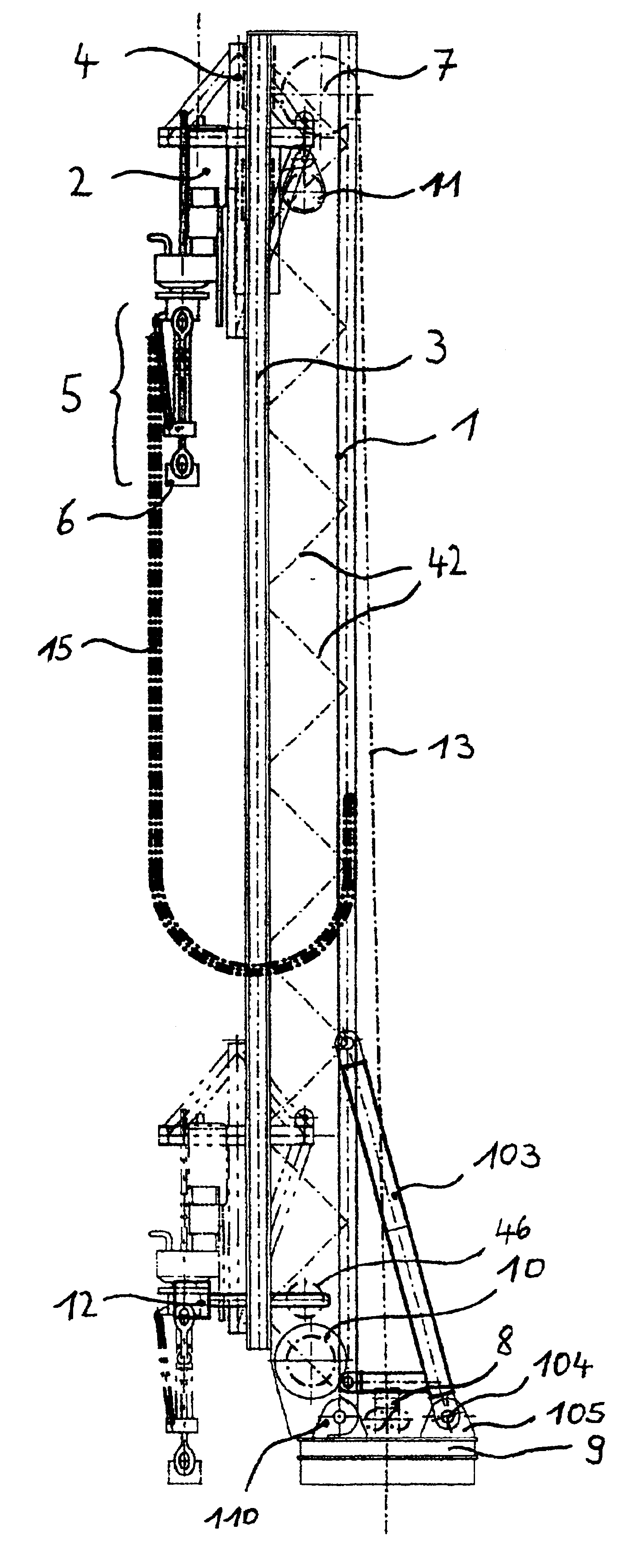
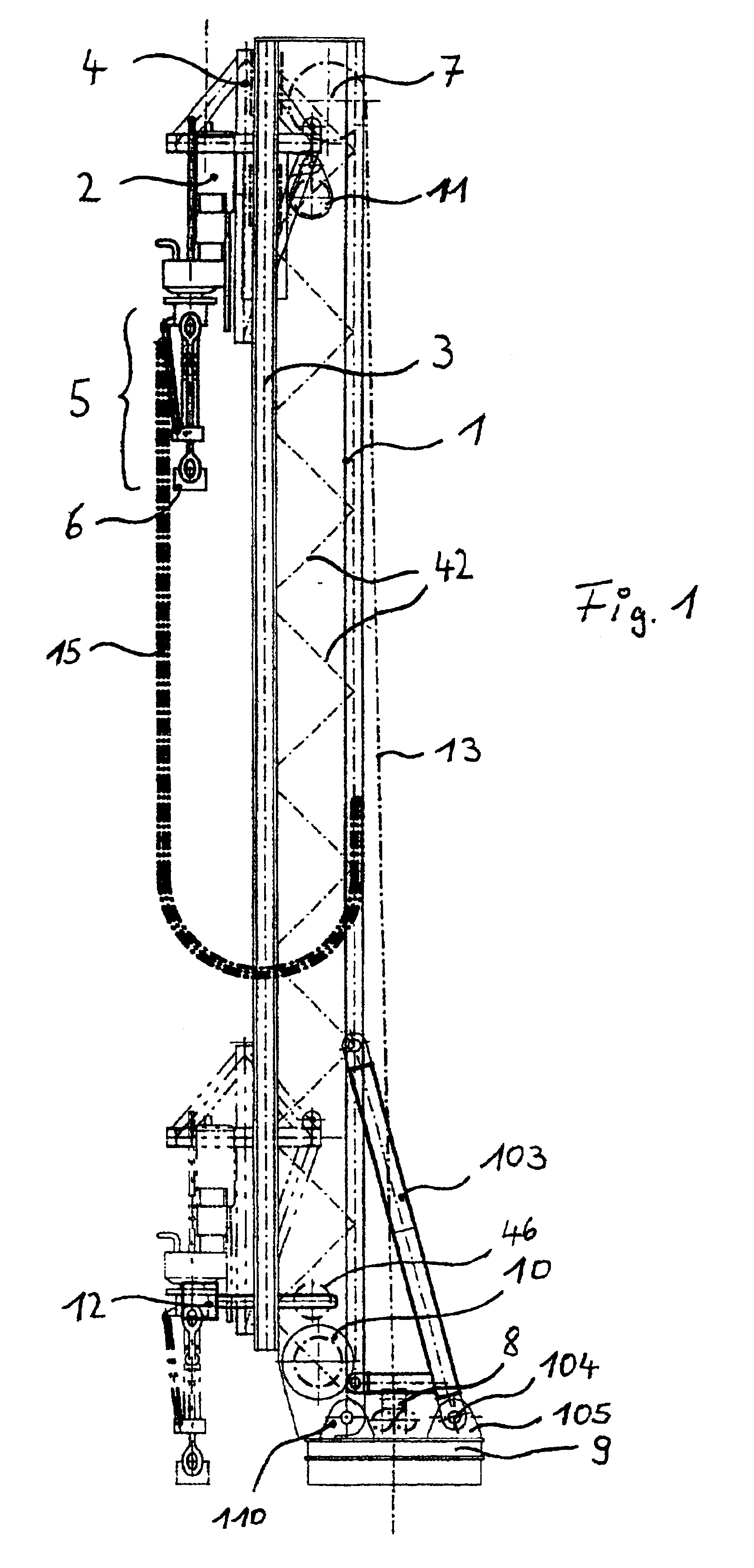
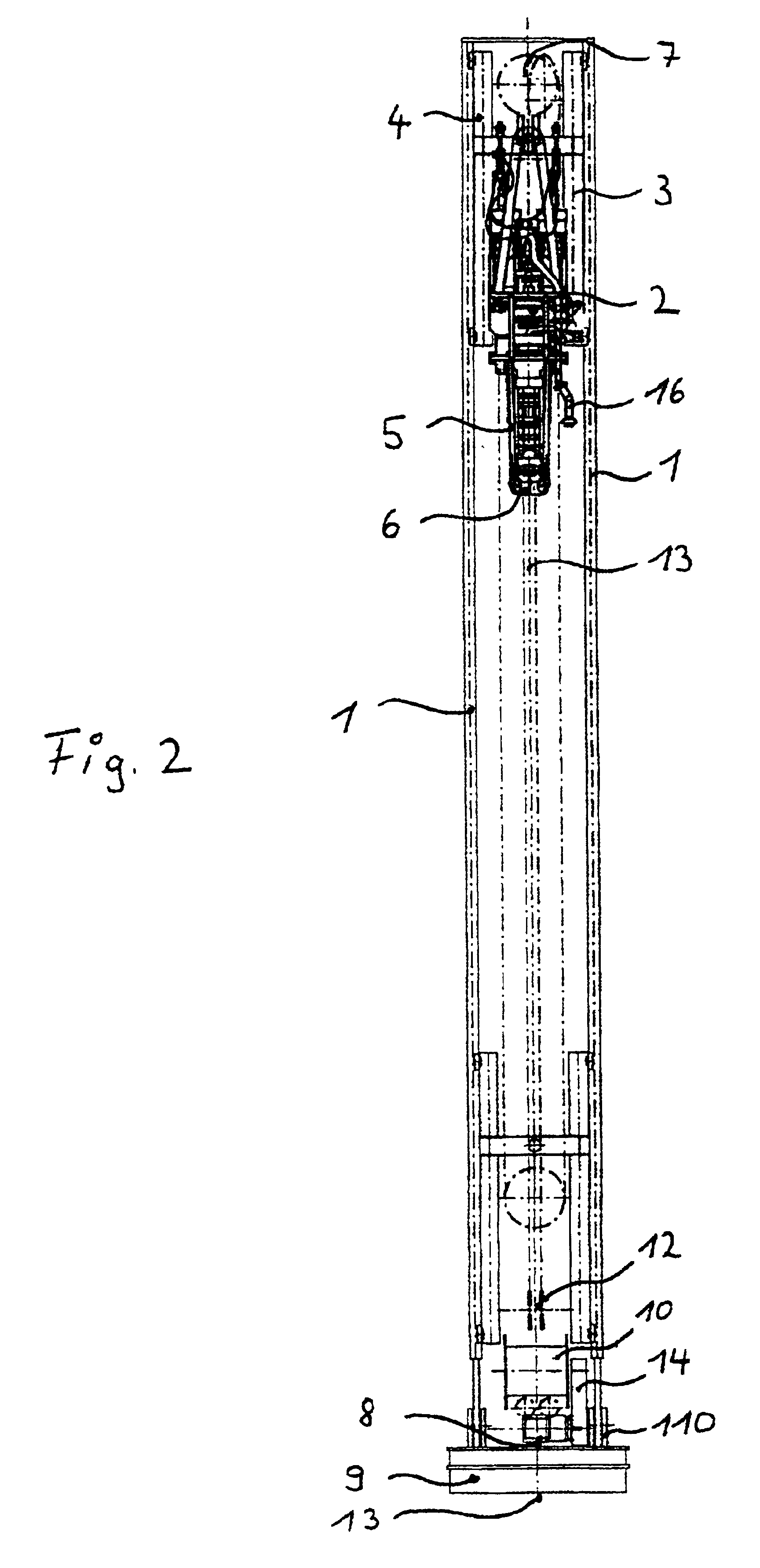
In FIGS. 1, 2, 4, 5, 6, 8, 9 and 10, the receiving frame 4 with top drive 2 and handling device 5 or the pipe handling device 23 are shown in two different positions, one position in each case being shown in broken lines. In the broken-line illustration of the receiving frame and the top drive, the return roller 11 is not shown.

FIG. 1 shows the lateral view of the base 1 with the top drive 2, the linear guide 3 attached to the base, the receiving frame 4 for the top drive, the handling device below the top drive 5 and the elevator for pipe acceptance. Below the top drive is optionally arranged a screwing and securing device, in order to screw a pipe feef in by means of the handling device fixedly to the shaft of the top drive, or, for example during the removal of the pipe, to break the connection again between top drive and pipe. Struts 42 of the base 1 are indicated, these improving the statics of the base.

Also shown in the drawing is the crown block 7, which is integrated in the ...


PUM


Abstract

A drilling machine and drilling rig for exploratory drillings and producing wells, include a base mounting atop drive, and a multifunctional gripper for gripping drilling pipe from a stock and to be raised on the base for eventual positions positioning at a well center, an elevator being provided below the top drive. The base can be rotatably mounted and have a live ring at a base lower end region, the base being rotated to the pipe stock location and being rotatable to a well center as well. A drilling pipe upper end when raised on the base can be connected to the top drive, and an iron roughneck on a rig floor can be used to connect a pipe lower end to a pipe section in the well. Where two drilling machine are used, one can be used for actual drilling at the well center, and the second supplied with pipework for the operation.

Description

BACKGROUND OF THE INVENTION1. Field of the InventionThe invention relates to a drilling machine for a drilling rig and to a drilling rig which can be used for exploratory drillings and producing wells, especially in hydrocarbon deposits. This drilling machine can be used both onshore and offshore. The invention further relates to a method for sinking such a well.2. Description of the Related ArtModern drilling rigs according to the prior art consist of a large number of components, such as a drawworks, an iron roughneck, a rig floor, a pipe handling system, a pipe rack, a crown block with a traveling block and a top drive, and a pipe ramp and a catwalk for the drilling pipes and various auxiliary devices for handling.Such drilling rigs have the disadvantage that they consist of a large number of components which, because of the constant changing of the drilling location of the drilling rigs, entail elaborate and costly logistics and large numbers of personnel. In addition, the indiv...

Claims


Application Information

Patent Timeline
IPC IPC(8): E21B19/00E21B19/20E21B15/00
CPCE21B19/20E21B15/00
Inventor DIRKS, THORSTENMOSS, JOHANNES
Owner BENTEC DRILLING & OILFIELD SYST
Why Eureka
Try Eureka