Methods of manufacturing illumination systems

a technology of illumination system and manufacturing method, applied in the field of lighting, can solve the problems of inefficiency of machined or embossed features, limited installation and use of panel lighting force,

Inactive Publication Date: 2012-03-01
SNAPTRACK
View PDF1 Cites 13 Cited by
  • Summary
  • Abstract
  • Description
  • Claims
  • Application Information

AI Technical Summary

Benefits of technology

[0010]The system, method, and devices of the invention each have several aspects, no single one of which is solely responsible for its desirable attributes. Without limiting the scope of this invention, its more prominent features will now be discus

Problems solved by technology

While the thickness of panel lighting is generally significantly less than corresponding width and length dimensions, it is frequently the case that t

Method used


Image

  • Methods of manufacturing illumination systems
  • Methods of manufacturing illumination systems
  • Methods of manufacturing illumination systems

Examples


first embodiment

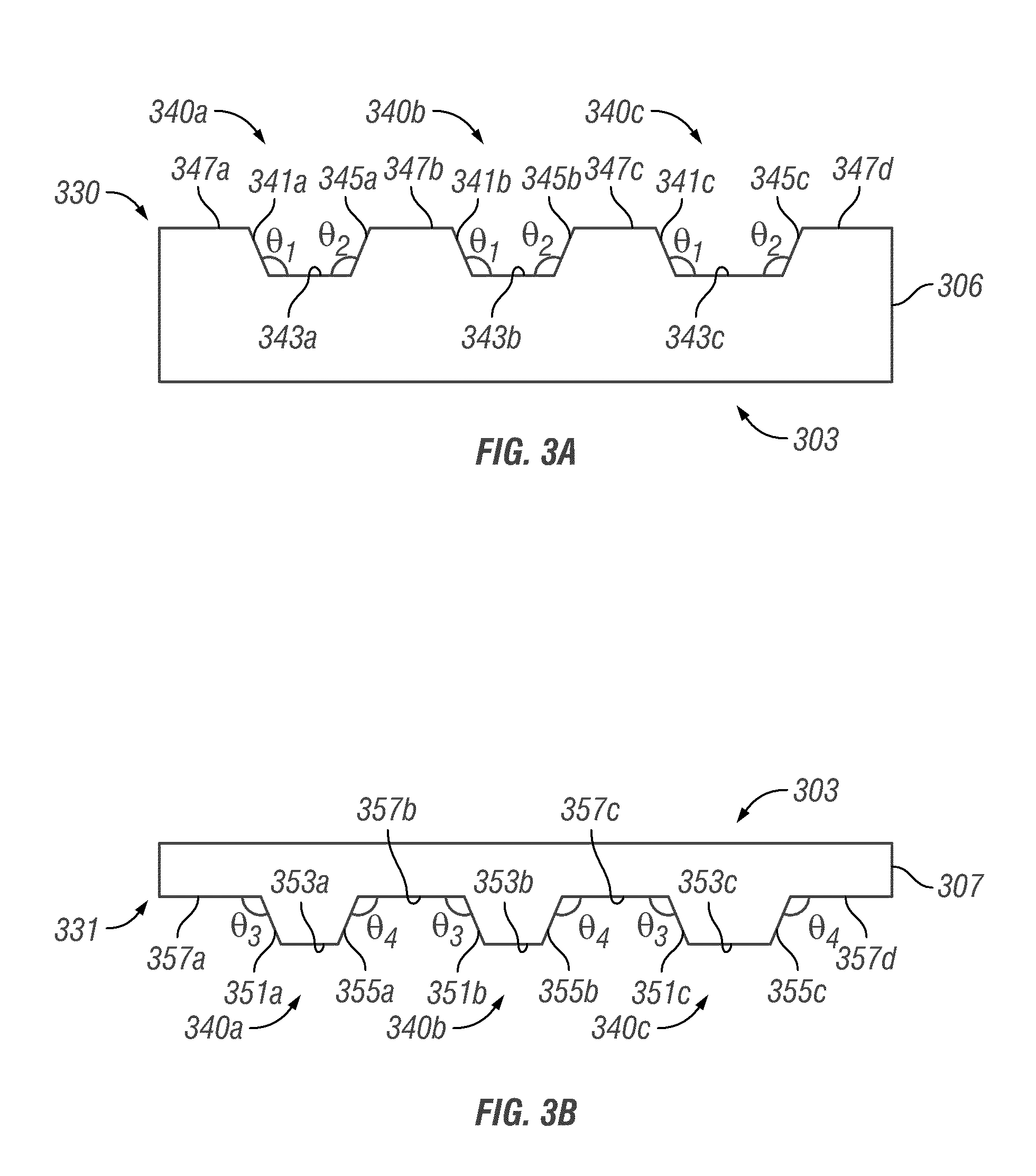
[0020]FIG. 3A is a cross-section of a base layer used to manufacture an illumination system having a plurality of re-entrant turning features.

[0021]FIG. 3B is a cross-section of a cover layer used to manufacture the first embodiment of an illumination system.

[0022]FIG. 3C is a cross-section of the base layer of FIG. 3A shown with the cover layer of FIG. 3B with a coupling layer applied to the cover layer.

[0023]FIG. 3D is a cross-section of the first embodiment of an illumination system having a plurality of re-entrant turning features formed between the cover layer of FIG. 3B and the base layer of FIG. 3A.

[0024]FIG. 3E is a block diagram schematically illustrating an embodiment of a method of manufacturing the light panel schematically illustrated in FIG. 3D.

second embodiment

[0025]FIG. 4A is a cross-section of a base layer used to manufacture an illumination system having a plurality of re-entrant turning features.

[0026]FIG. 4B is a cross-section of a prismatic block used to manufacture the second embodiment of an illumination system.

[0027]FIG. 4C is a cross-section of a set of prismatic blocks from FIG. 4B shown with the base layer of FIG. 4A and a coupling layer applied to each of the plurality of prismatic blocks.

[0028]FIG. 4D is a cross-section of the second embodiment of an illumination system having a plurality of re-entrant turning features formed between the prismatic blocks of FIG. 4B and the base layer of FIG. 4A.

[0029]FIG. 4E is a block diagram schematically illustrating an embodiment of a method of manufacturing the light panel schematically illustrated in FIG. 4D.

third embodiment

[0030]FIG. 5A is a cross-section of a base layer used to manufacture an illumination system having a plurality of re-entrant turning features.

[0031]FIG. 5B is a cross-section of a first prismatic block used to manufacture the third embodiment of an illumination system.

[0032]FIG. 5C is a cross-section of a second prismatic block used to manufacture the third embodiment of an illumination system.

[0033]FIG. 5D is a cross-section of a set of the first prismatic blocks from FIG. 5B and the second prismatic blocks from FIG. 5C shown with the base layer of FIG. 5A and a coupling layer applied to each of the prismatic blocks.

[0034]FIG. 5E is a cross-section of the third embodiment of an illumination system having a plurality of re-entrant turning features formed between the prismatic blocks of FIGS. 5B and 5C and the base layer of FIG. 5A.

[0035]FIG. 5F is a block diagram schematically illustrating an embodiment of a method of manufacturing the light panel schematically illustrated in FIG. 5...


PUM

PropertyMeasurementUnit
Angleaaaaaaaaaa
Refractionaaaaaaaaaa

Abstract

Methods of manufacturing light panels having at least one re-entrant turning feature. In one embodiment, a method of manufacturing a light panel includes providing a base layer, providing a cover layer, and coupling the cover layer to the base layer to form at least one re-entrant turning feature between the base layer and the cover layer. In another embodiment, a method of manufacturing a light panel includes providing a base layer, forming at least one receiving space in the base layer, providing at least one prismatic block, and coupling at least a portion of the prismatic block into the receiving space such that re-entrant turning features are formed between the prismatic block and the base layer.

Description

BACKGROUND[0001]1. Field of the Invention[0002]The invention relates to the field of lighting, and in particular, light extraction in illumination systems.[0003]2. Description of the Related Art[0004]A variety of architectural lighting configurations are utilized to provide artificial illumination in a wide variety of indoor and / or outdoor locations. Such illumination systems can include fixed and portable architectural lighting. Various configurations can employ technologies such as incandescent, fluorescent, and / or light emitting diode based light sources.[0005]One type of architectural lighting configuration can be referred to generally as panel lighting. Panel lights may include, for example, fluorescent lighting in a light box behind a plastic lenticular panel. Panel lighting is often configured as planar and square or rectangular and having width and length dimensions significantly greater than a thickness dimension. While the thickness of panel lighting is generally significa...

Claims


Application Information

Patent Timeline
IPC IPC(8): H05K13/00
CPCG02B6/0036G02B6/0038G02B6/0053G02B6/0065B23P11/00Y10T29/49002Y10T29/49131Y10T29/49904Y10T29/49826Y10T29/49155Y10T29/49208
Inventor CHUI, CLARENCESETHI, GAURAVGRIFFITHS, JONATHAN CHARLESKOTHARI, MANISH
Owner SNAPTRACK
Why Eureka
Try Eureka