
Apparatus and method for displaying three-dimensional (3D) object

a three-dimensional, object technology, applied in the field of apparatus and a method for displaying a three-dimensional (3d) object, can solve the problems of awkward applicability and limited application range of technology

Inactive Publication Date: 2012-03-01
PANTECH CO LTD
View PDF3 Cites 25 Cited by
  • Summary
  • Abstract
  • Description
  • Claims
  • Application Information

AI Technical Summary

Benefits of technology

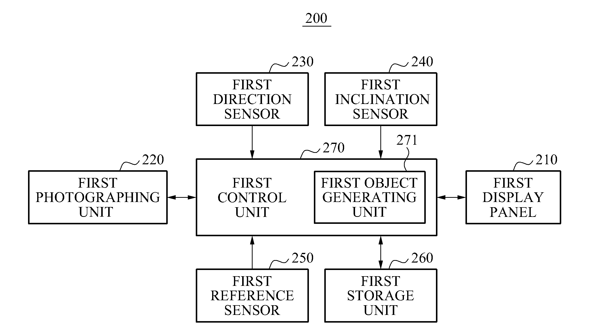
[0007]Exemplary embodiments of the present invention provide an apparatus and a method for displaying a three-dimensional (3D) object, which may provide a stereoscopic effect of a 3D object varying adaptively depending on a line of sight of a user.
[0009]Exemplary embodiments of the present invention provide an apparatus and the method for displaying a 3D object that may improve a display accuracy of a 3D object displayed based on a line of sight of a user using a small number of sensors, resulting in cost reduction and lightweight products.
[0010]Exemplary embodiments of the present invention provide an apparatus and the method for displaying a 3D object that may prevent a malfunction of a 3D menu even in a driving car through a stereoscopic feedback of a 3D object based on a line of sight of a user, resulting in an increased accuracy of motion recognition.
[0011]Exemplary embodiments of the present invention provide an apparatus and the method for displaying a 3D object that may recognize a change in a vanishing point based on a line of sight so that a 3D object may be displayed with fewer calculations.

Problems solved by technology

A typical 3D object display technology may provide a stereoscopic effect using separate images is caused by a difference in vision between a left eye and a right eye; however, the technology may show a same display even if a line of sight of a user changes.
However, the technology may have an application range limited to a fixed equipment, such as a television.
If the 3D object display technology using a head tracking scheme is applied to a mobile equipment, such as a portable appliance, an additional device may be needed, for example, glasses with an infrared device, resulting in awkward applicability.

Method used


Image

  • Apparatus and method for displaying three-dimensional (3D) object
  • Apparatus and method for displaying three-dimensional (3D) object
  • Apparatus and method for displaying three-dimensional (3D) object

Examples


Embodiment Construction

[0028]The invention is described more fully hereinafter with reference to the accompanying drawings, in which embodiments of the invention are shown. This invention may, however, be embodied in many different forms and should not be construed as limited to the embodiments set forth herein. Rather, these embodiments are provided so that this disclosure is thorough, and will fully convey the scope of the invention to those skilled in the art. In the drawings, the size and relative sizes of layers and regions may be exaggerated for clarity. Like reference numerals in the drawings denote like elements.

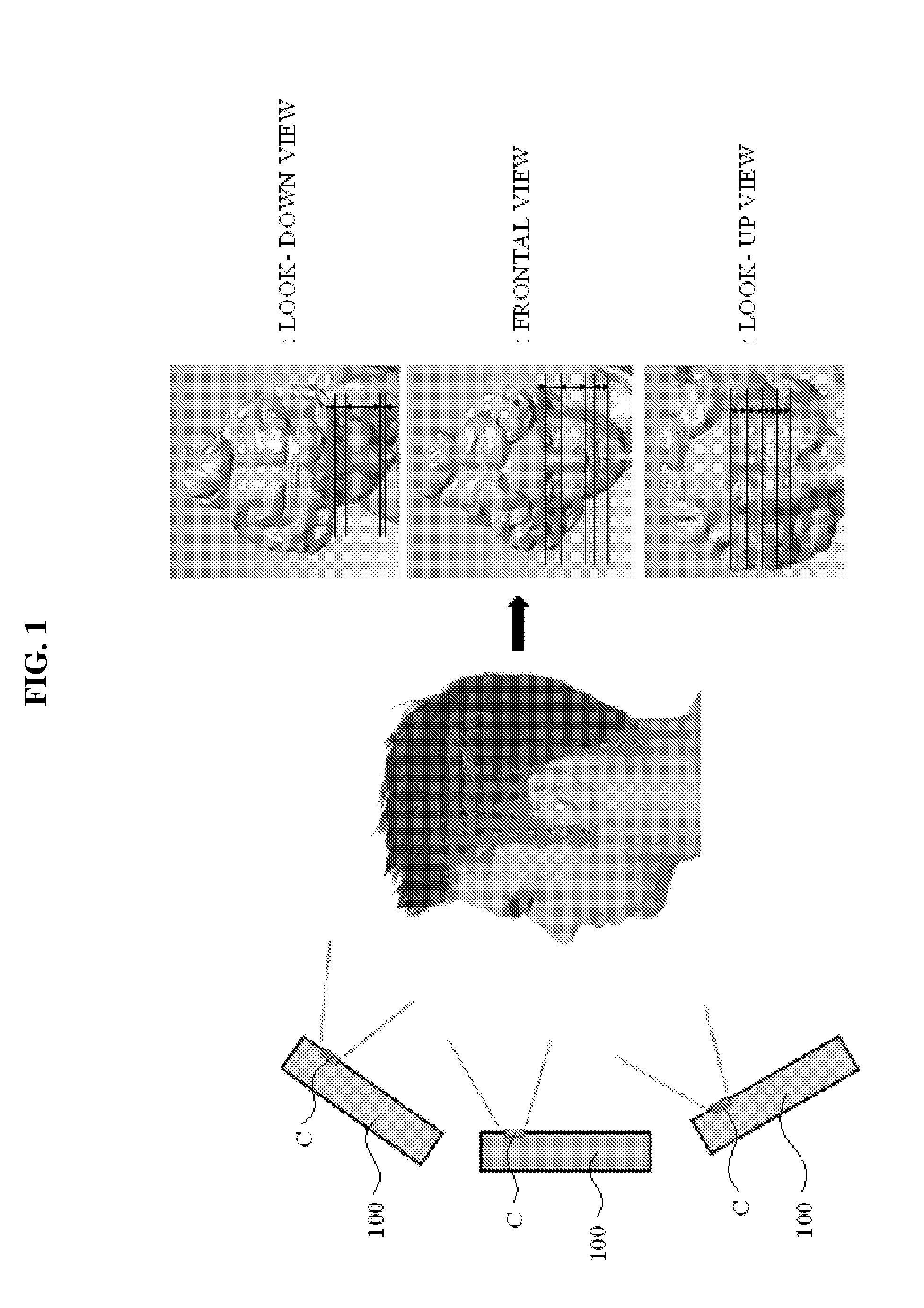
[0029]FIG. 1 is illustrates a method for measuring a facial proportion data according to an exemplary embodiment of the present invention.

[0030]Generally, a user of an apparatus 100 with camera functionality may be limited to one user. To measure facial proportion data, the apparatus 100 may photograph the face of a user using an embedded camera C. In this instance, the user may photograph...


PUM


Abstract

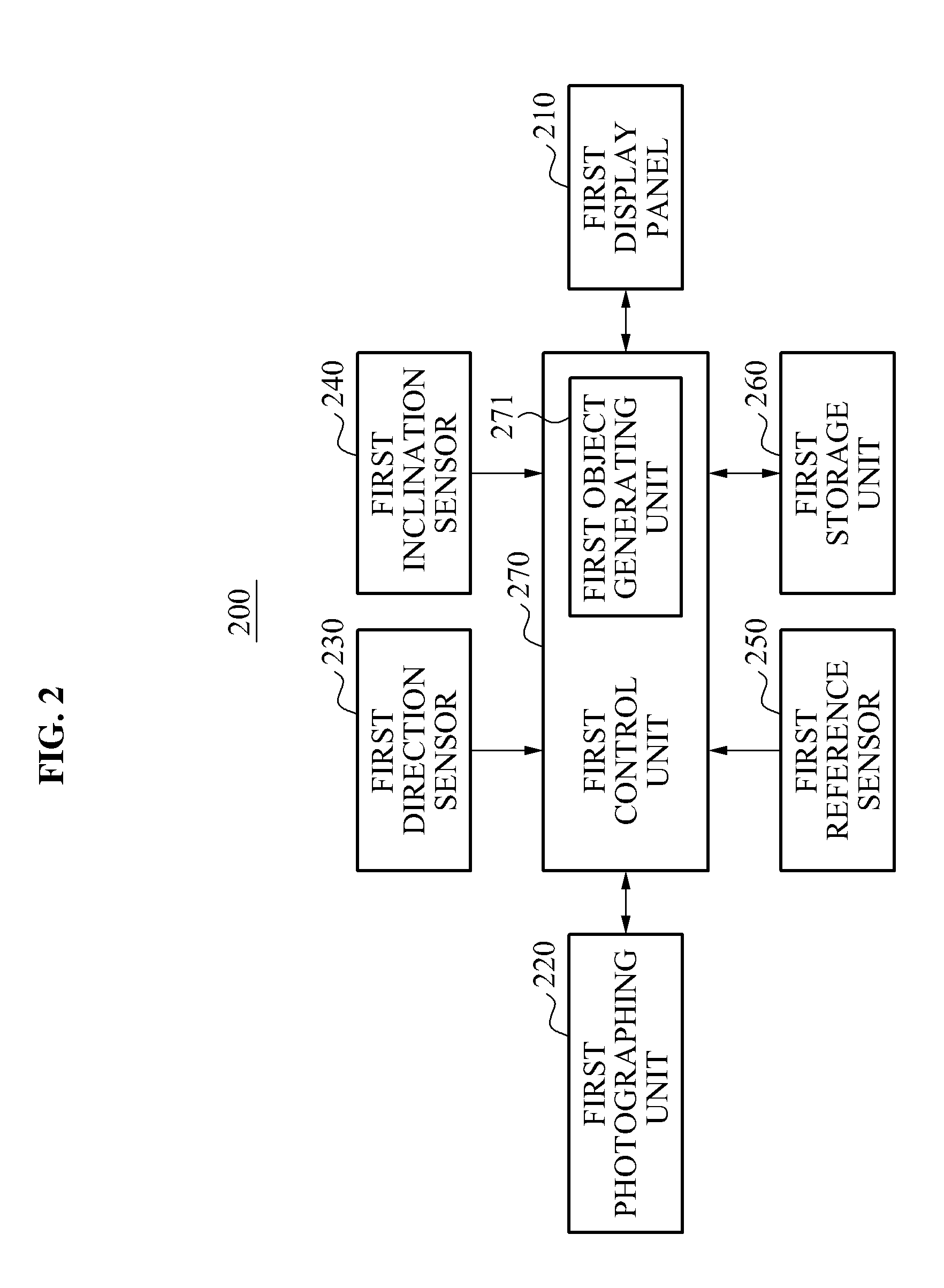
Provided are an apparatus and a method for displaying a three-dimensional (3D) object. The apparatus may include a display panel to display a 3D object having plural faces, an object generating unit to rotate the displayed 3D object in a rotation direction of the apparatus to display a second face of the 3D object toward the user if at least one of a first operation and a second operation occurs, the first operation being that the apparatus is rotated while a user is touching a first face of the plural faces of the 3D object and the second operation being that the face of the user is rotated while the user is touching the first face of the plural faces of the 3D object, and a control unit to perform a function mapped to the other face displayed toward the user.

Description

CROSS-REFERENCE TO RELATED APPLICATION[0001]This application claims priority from and the benefit under 35 U.S.C. §119(a) of Korean Patent Application No. 10-2010-0085446, filed on Sep. 1, 2010, which is hereby incorporated by reference for all purposes as if fully set forth herein.BACKGROUND[0002]1. Field[0003]Exemplary embodiments of the present invention relate to an apparatus and a method for displaying a three-dimensional (3D) object.[0004]2. Discussion of the Background[0005]A user terminal may display various menus using a three-dimensional (3D) object. A typical 3D object display technology may provide a stereoscopic effect using separate images is caused by a difference in vision between a left eye and a right eye; however, the technology may show a same display even if a line of sight of a user changes. That is, a typical 3D object display technology may show the same user interface (UI) regardless of a location of a user.[0006]Conventionally, a 3D object display technolog...

Claims


Application Information

Patent Timeline
Patent Type & Authority Applications(United States)
IPC IPC(8): G06F3/048
CPCG06F3/012G06F2203/04802G06F3/04815
Inventor LIM, JONG U.
Owner PANTECH CO LTD
Learn More