Litz heating antenna

a technology of heating antenna and geological formation, which is applied in the direction of electric/magnetic/electromagnetic heating, subaqueous/subterranean adaption, and well accessories. it can solve the problems of difficult use of steam in permafrost regions, inability to drill and refine the method used in extracting standard crude oil,

Active Publication Date: 2012-03-15
HARRIS CORP
View PDF11 Cites 19 Cited by
  • Summary
  • Abstract
  • Description
  • Claims
  • Application Information

AI Technical Summary

Problems solved by technology

Because of the extremely high viscosity of bituminous ore, oil sands, oil shale, tar sands, and heavy oil, the drilling and refinement methods used in extracting stand

Method used


Image

  • Litz heating antenna
  • Litz heating antenna
  • Litz heating antenna

Examples


Embodiment Construction

[0039]The subject matter of this disclosure will now be described more fully, and one or more embodiments of the invention are shown. This invention may, however, be embodied in many different forms and should not be construed as limited to the embodiments set forth herein. Rather, these embodiments are examples of the invention, which has the full scope indicated by the language of the claims.

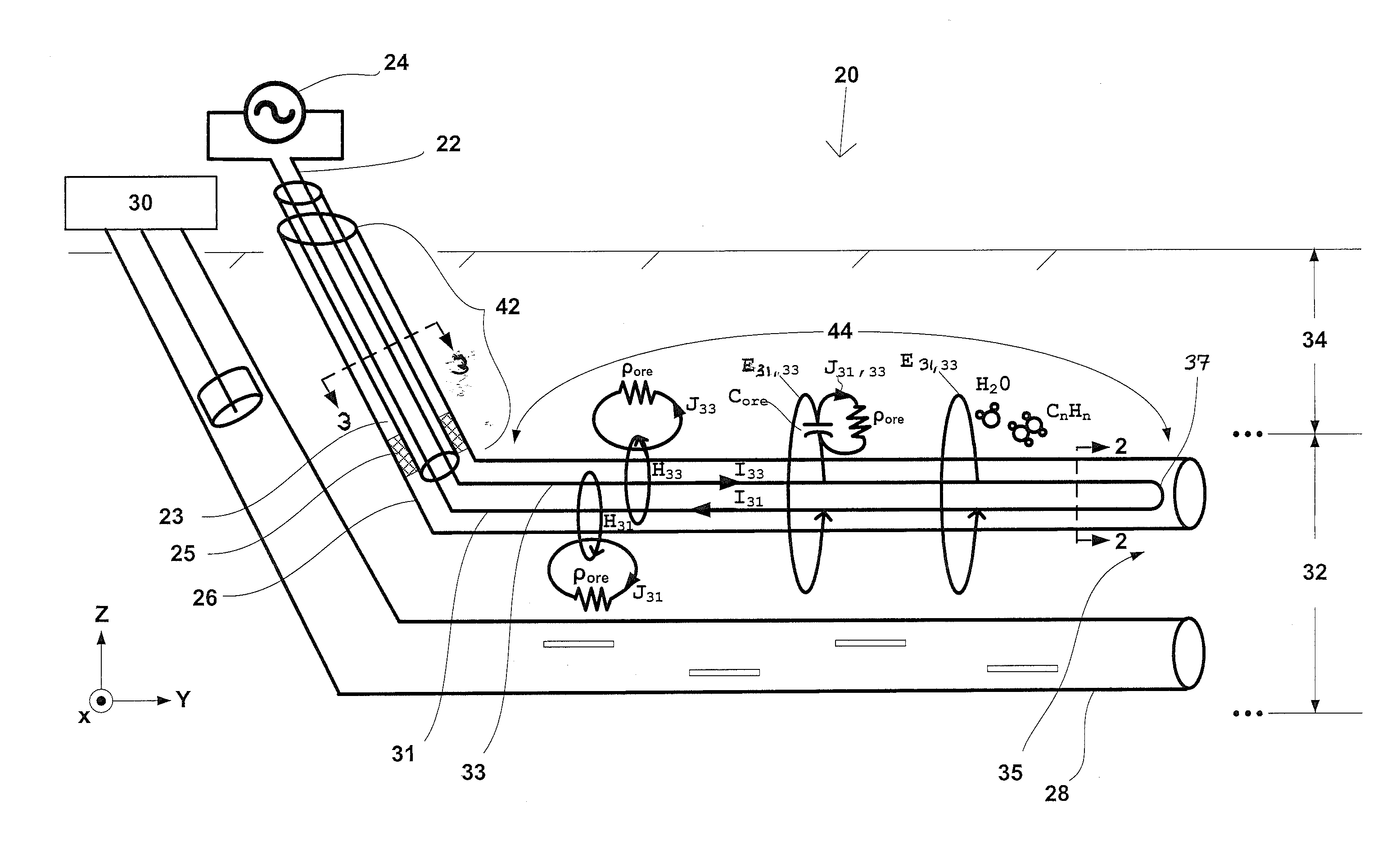
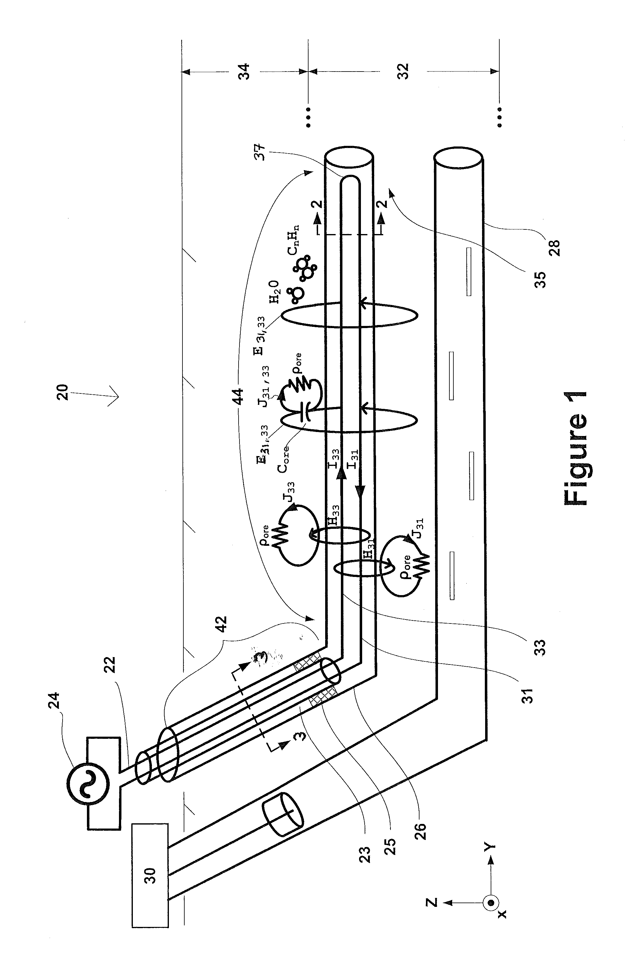
[0040]In FIG. 1 an embodiment of the present invention is shown as a system for heating a geological formation and extracting hydrocarbons, generally indicated as 20. The system 20 includes at least an applicator 22 connected to an RF transmitter source 24, an applicator bore 26, an extraction bore 28, and a pump 30. The applicator bore 26 is made in such a way that it extends into the formation 32. The applicator 22 is located inside the applicator bore 26 and positioned to radiate or transduce electromagnetic energies into the formation 32. The extraction bore 28 is positioned below the appl...


PUM


Abstract

An electromagnetic heating applicator is disclosed. The applicator includes a first strand and a second strand, each of which has an insulated portion, a bare portion, and is made up of at least one wire. The first and second strands are braided, twisted, or both braided and twisted together such that the bare portion of each strand is adjacent to the insulated portion of the other strand. A system and method for heating a geological formation are also disclosed. The system includes an applicator in a bore that extends into a formation, an extraction bore connected to a pump and positioned under the first bore, and transmitting equipment connected to the applicator. The method includes the steps of providing the components of the system, connecting the applicator to RF power transmitting equipment, applying RF power to the applicator using the transmitting equipment, and pumping hydrocarbons out of the extraction bore.

Description

CROSS REFERENCE TO RELATED APPLICATIONS[0001]This specification is related to the following patent applications, identified by attorney docket numbers :[0002]GCSD-2261, H8531, 201000219[0003]GCSD-2255, H8530, 201000190[0004]GCSD-2222, H8524, 200900964[0005]GCSD-2249, H8523, 201000143[0006]GCSD-2236, H8522, 200901090filed on the dates specified above, each of which is incorporated by reference here.[0007]This specification is also related to U.S. Serial Nos:[0008]Ser. No. 12 / 396,284, filed Mar. 2, 2009[0009]Ser. No. 12 / 396,247, filed Mar. 2, 2009[0010]Ser. No. 12 / 396,192, filed Mar. 2, 2009[0011]Ser. No. 12 / 396,057, filed Mar. 2, 2009[0012]Ser. No. 12 / 396,021, filed Mar. 2, 2009[0013]Ser. No. 12 / 395,995, filed Mar. 2, 2009[0014]Ser. No. 12 / 395,953, filed Mar. 2, 2009[0015]Ser. No. 12 / 395,945, filed Mar. 2, 2009[0016]Ser. No. 12 / 395,918, filed Mar. 2, 2009each of which is incorporated by reference here.BACKGROUND OF THE INVENTION[0017]The present invention relates to heating a geologi...

Claims


Application Information

Patent Timeline
IPC IPC(8): H05B6/10H05B6/02
CPCH05B2214/03H01Q1/04H05B6/54E21B43/2401E21B43/2408
Inventor PARSCHE, FRANCIS EUGENE
Owner HARRIS CORP
Why Eureka
Try Eureka