
Limiting mechanism for lifting and lowering blind

Inactive Publication Date: 2012-03-15
CHICOLOGY
View PDF1 Cites 15 Cited by
  • Summary
  • Abstract
  • Description
  • Claims
  • Application Information

AI Technical Summary

Benefits of technology

[0005]In view of the aforesaid drawback of the conventional limiting mechanism for lifting and lowering a blind, the inventor of the present invention believes that the conventional blind has room for improvement. Thus, the inventor of the present invention endeavors to improve the conventional blind from the inventor's experience of the related industry. Eventually, the inventor puts forth a limiting mechanism for lifting and lowering a blind that works without any tractional cord and features ease of use and enhanced user safety.
[0006]It is a primary objective of the present invention to provide a limiting mechanism for lifting and lower a blind. The limiting mechanism is integrated into a blind body when in use, so as for a shade to be lifted or lowered when an external force is exerted thereon by a user, wherein the lifting or lowering of the shade is effectuated by a resilient unit, a recoiling roller, and a tractional unit in conjunction with the external force exerted by the user, so as to dispense with a tractional cord and enhance ease of use and use safety.
[0013]The present invention provides a limiting mechanism for lifting and lowering a blind. The limiting mechanism is integrated into a blind body when in use, so as for a shade to be lifted or lowered when an external force is exerted thereon by a user, wherein the lifting or lowering of the shade is effectuated by a resilient unit, a recoiling roller, and a tractional unit in conjunction with the external force exerted by the user, so as to dispense with a tractional cord and enhance ease of use and use safety.

Problems solved by technology

The conventional blind has a drawback.
With a tractional cord on the neck, a toddler may end up in strangulation.
Hence, tractional cords of the conventional blind pose a serious threat to child safety.

Method used


Image

  • Limiting mechanism for lifting and lowering blind
  • Limiting mechanism for lifting and lowering blind
  • Limiting mechanism for lifting and lowering blind

Examples


Embodiment Construction

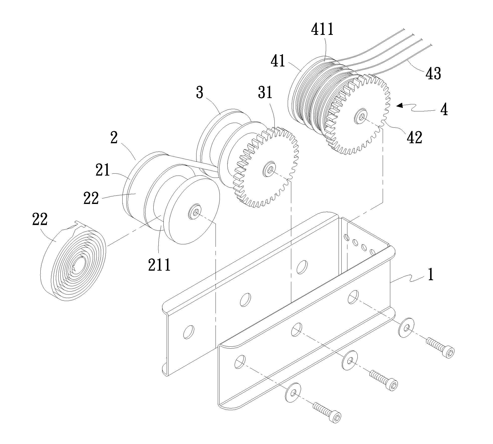
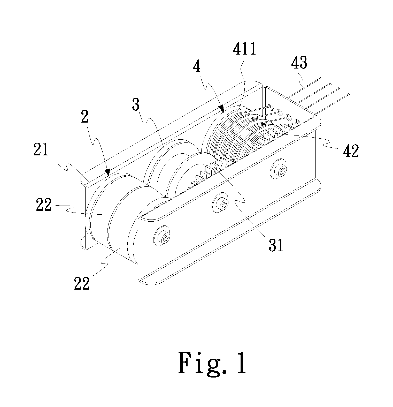
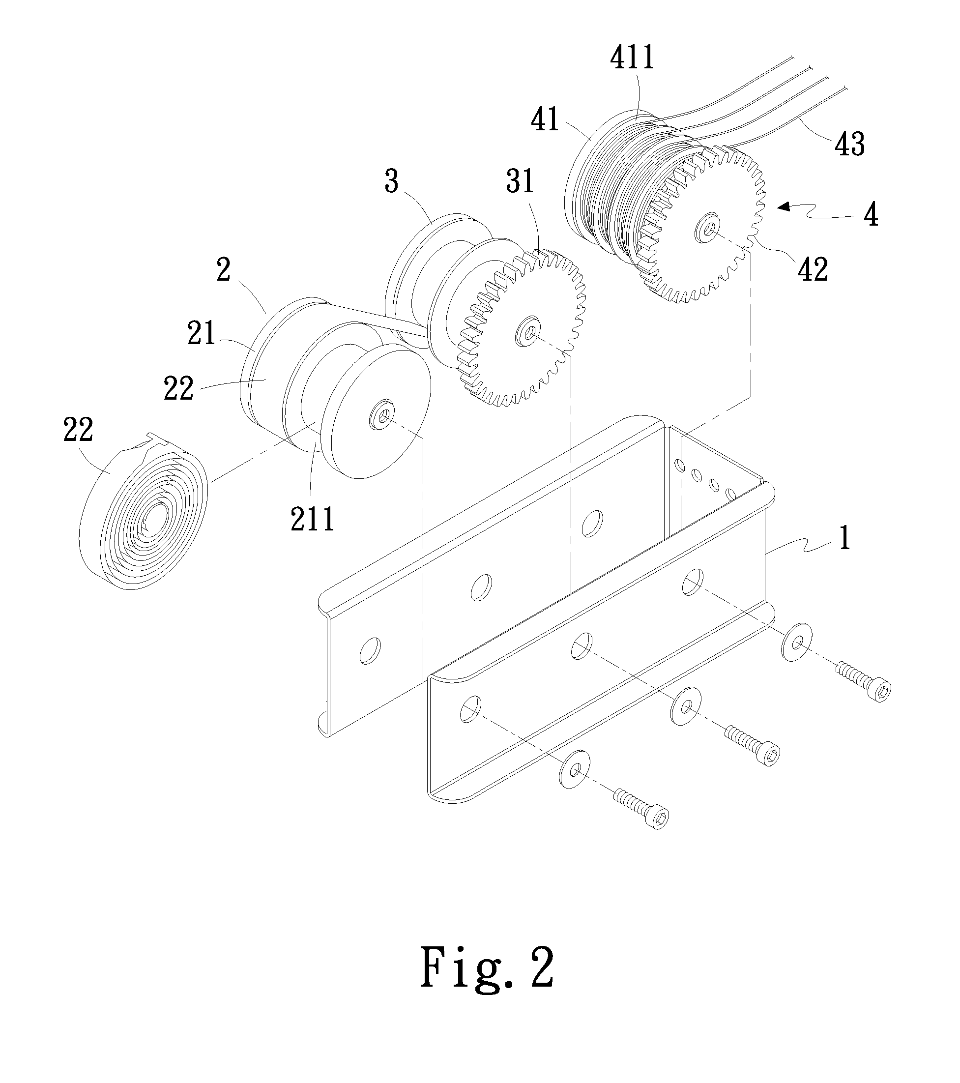
[0019]Referring to FIG. 1 and FIG. 2, there are shown a perspective view and an exploded view of the present invention, respectively. As shown in the drawings, a limiting mechanism for lifting and lowering a blind comprises a carrier 1, a resilient unit 2, a recoiling roller 3, and a tractional unit 4.

[0020]The carrier 1 is a frame.

[0021]The resilient unit 2 is movably disposed at one end of the carrier 1. The resilient unit 2 comprises a reel 21 and a plurality of constant force springs 22. The reel 21 has at least two spooling portions 211. The constant force springs 22 are disposed on the spooling portions 211, respectively. Each of the constant force springs 22 has one end coupled to the corresponding one of the spooling portions 211.

[0022]The recoiling roller 3 is movably disposed in the carrier 1 and positioned proximate to the resilient unit 2. A first gear member 31 is disposed on one side of the recoiling roller 3. Each of the constant force springs 22 has the other end cou...


PUM


Abstract

The present invention relates to a limiting mechanism for lifting and lowering a blind. The limiting mechanism includes a carrier; a resilient unit movably disposed at an end of the carrier; a recoiling roller movably disposed in the carrier and positioned proximate to the resilient unit; and a tractional unit movably disposed in the carrier and driven by the recoiling roller. The limiting mechanism is integrated into a blind body when in use, so as for a shade to be lifted or lowered when an external force is exerted thereon by a user, wherein the lifting or lowering of the shade is effectuated by the resilient unit, the recoiling roller, and the tractional unit in conjunction with the external force exerted by the user, so as to dispense with a tractional cord and enhance ease of use and use safety.

Description

FIELD OF THE INVENTION[0001]The present invention relates to limiting mechanisms for lifting and lowering a blind, and more particularly, to a limiting mechanism integrated into a blind body when in use, so as for a shade to be lifted or lowered when an external force is exerted thereon by a user, wherein the lifting or lowering of the shade is effectuated by a resilient unit, a recoiling roller, and a tractional unit in conjunction with the external force exerted by the user, so as to dispense with a tractional cord and enhance ease of use and use safety.BACKGROUND OF THE INVENTION[0002]A conventional blind (such as a Roman blind) comprises an upper beam, an elevating unit, and a shade coupled to the bottom of the upper beam. The elevating unit has a plurality of tractional cords and lifting cords. The shade comprises a plurality of slats. At least a plurality of holes are formed in each of the slats. The holes are lined up and penetrated by the lifting cords in a manner that the l...

Claims


Application Information

Patent Timeline
IPC IPC(8): B65H75/48B65H75/30B65H75/44
CPCE06B2009/3222E06B9/322
Inventor CHEN, JU-HUAI
Owner CHICOLOGY
Learn More