Photometry device

a technology of photometry and light, applied in the field of photometry devices, can solve problems such as not being widely distributed, and achieve the effect of improving the brightness measurement accuracy

Inactive Publication Date: 2012-03-29
PANASONIC CORP
View PDF1 Cites 1 Cited by
  • Summary
  • Abstract
  • Description
  • Claims
  • Application Information

AI Technical Summary

Benefits of technology

[0006]In view of the above, an object of the present invention is to provide a photometry device capable of improving its measurement accuracy of brightness in mesopic vision.
[0009]The photometry device of the invention can improve measurement accuracy of brightness in mesopic vision.

Problems solved by technology

However, since a relationship between the spectral luminous efficiency in mesopic vision and the color temperature of the light source is indefinite, such conventional example is not widely spread due to its low validity of the measurement value.

Method used


Image

  • Photometry device
  • Photometry device
  • Photometry device

Examples


first embodiment

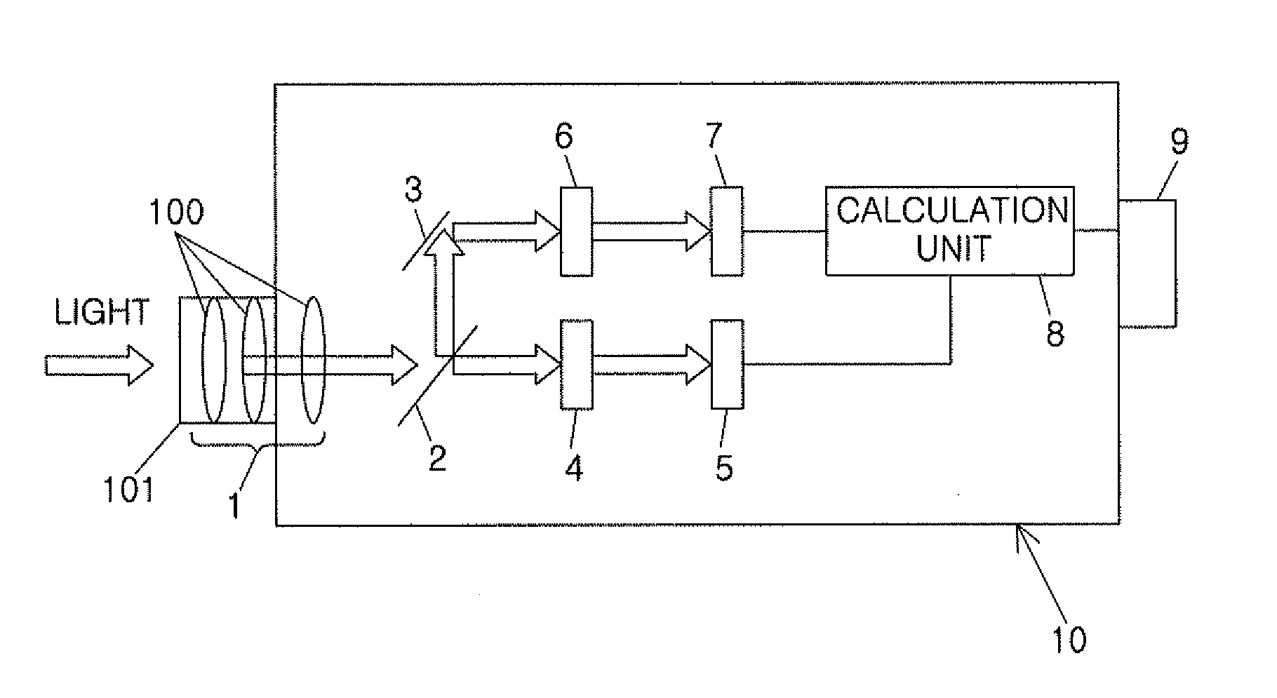
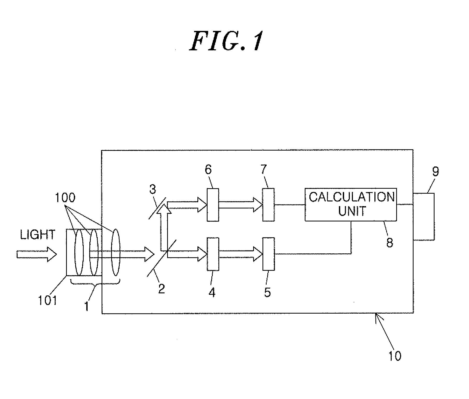
[0014]A photometry device of the present embodiment is, as shown in FIG. 1, provided with an optical part 1, a half mirror 2, a mirror 3, a first light filter 4, a first photoelectric converter 5, a second light filter 6, a second photoelectric converter 7, a calculation part 8, a display 9, and a housing 10.

[0015]The housing 10 has a box-like shape and is made of a synthetic resin or a metal. Light is introduced in the housing 10 through a hole opened in the left side thereof.

[0016]The optical part 1 includes a plurality of convex lenses 100; and a cylindrical body 101 supporting the convex lenses 100 and closing the hole of the housing 10. Accordingly, the light introduced through the hole is converged by the convex lens 100 of the optical part 1.

[0017]The half mirror 2 is disposed on an optical path of the optical part 1, and splits the light converged by the optical part 1 into two parts. On one optical path branched by the half mirror 2, the first light filter 4 is disposed. Th...

second embodiment

[0025]A photometry device of the present embodiment, as shown in FIG. 3, includes: a spectral filter 11 for dispersing incident light; a measuring part 12 for measuring intensities (luminance) of the lights dispersed into a plurality of wavelength bands at each wavelength band; and a calculation part 13 for calculating mesopic vision luminance. The same reference numerals are assigned to the common components to the photometry device of the first embodiment, and the description thereof will be omitted.

[0026]The spectrum filter 11 is configured of a prism, and divides (disperses) incident light into a plurality of wavelength bands by utilizing its different refractive indexes depending on the wavelengths of the light. The measuring part 12 has a plurality of photoelectric transducers (not shown) corresponding to each of the wavelength bands of the light dispersed by the spectrum filter 11, and a plurality of amplifiers (not shown) amplifying output voltages of the respective photoele...


PUM


Abstract

In a photometry device, photopic vision luminance Lp is measured by a first luminance measuring unit including a first light filter 4 and a first photoelectric converter 5, and scotopic vision luminance Ls is measured by a second luminance measuring unit including a second light filter 6 and a second photoelectric converter 7. A calculation part 8 calculates mesopic vision luminance Lmes based on a measurement value (photopic vision luminance Lp) of the first luminance measuring unit and a ratio of a measurement value (scotopic vision luminance Ls) of the second luminance measuring unit to the measurement value (photopic vision luminance Lp) of the first luminance measuring unit. Consequently, the photometry device can improve measurement accuracy of the brightness (mesopic vision luminance) in mesopic vision.

Description

FIELD OF THE INVENTION[0001]The invention relates to a photometry device for measuring brightness in scotopic and mesopic vision.BACKGROUND OF THE INVENTION[0002]Spectral luminous efficiency of human eyes varies in photopic, scotopic, and mesopic visions. In photopic vision, cone cells are in function to sense colors. In scotopic vision, although colors are not perceivable because no cone cells are in function, rod cells operate to improve color-sensitivity. In mesopic vision, which is an intermediate state of the photopic vision and the scotopic vision, both the cone and rod cells are in function. Herein, the spectral luminous efficiency in photopic vision has a peak wavelength of about 555 nm. On the other hand, the spectral luminous efficiency in scotopic vision has a shifted peak wavelength of about 507 nm. Such phenomenon is well known as “Purkinje phenomenon.”[0003]As an index of the brightness sensed by human eyes, luminance and illuminance are typically employed. As for conv...

Claims


Application Information

Patent Timeline
Patent Type & Authority Applications(United States)
IPC IPC(8): A61B3/14
CPCG01J1/04G01J1/0477G01J1/1626A61B3/1225A61B3/00A61B3/1208G01J1/4228
Inventor SAITO, TAKASHINOGUCHI, HIROKITODA, NAOHIROTSUKITANI, AYAKONISHIOKA, KOUJITAKASIMA, AKIRAIBARA, KAORUYAMAZOE, KENSUKEKUBO, HIROEKARASAWA, YOSHINORI
Owner PANASONIC CORP
Why Eureka
Try Eureka