Electrical card connector with improved contacts arrangement

Inactive Publication Date: 2012-04-05
HON HAI PRECISION IND CO LTD
View PDF6 Cites 0 Cited by
  • Summary
  • Abstract
  • Description
  • Claims
  • Application Information

AI Technical Summary

Benefits of technology

[0006]An object of the present invention is to provide an electrical card connector wi

Problems solved by technology

However, a user often place the upper side of the card upwardly when inserting a card to the card receiving space, and such error operation my damage the card connector.

Method used


Image

  • Electrical card connector with improved contacts arrangement
  • Electrical card connector with improved contacts arrangement
  • Electrical card connector with improved contacts arrangement

Examples


Embodiment Construction

[0016]Reference will now be made in detail to the preferred embodiment of the present invention.

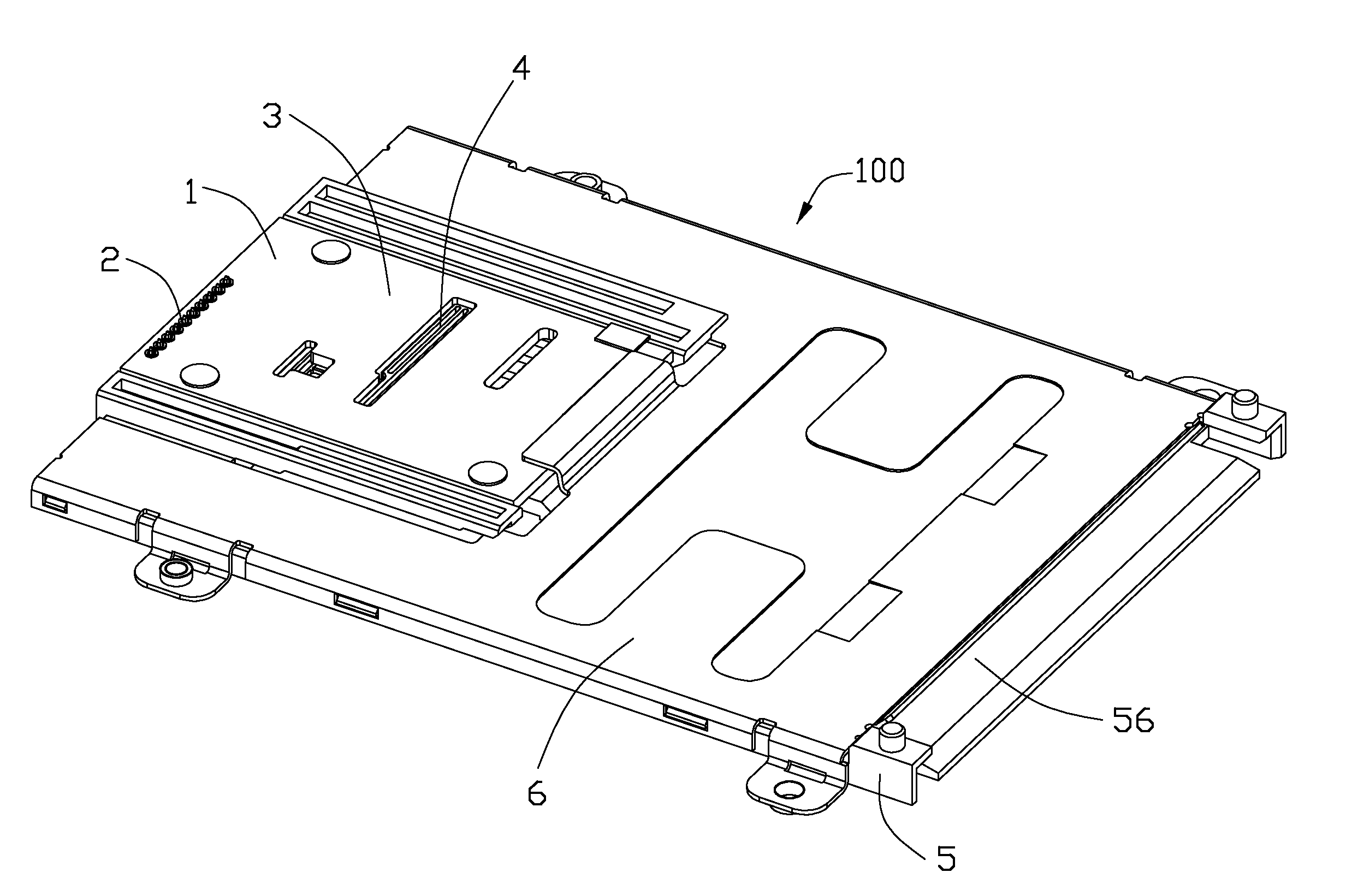
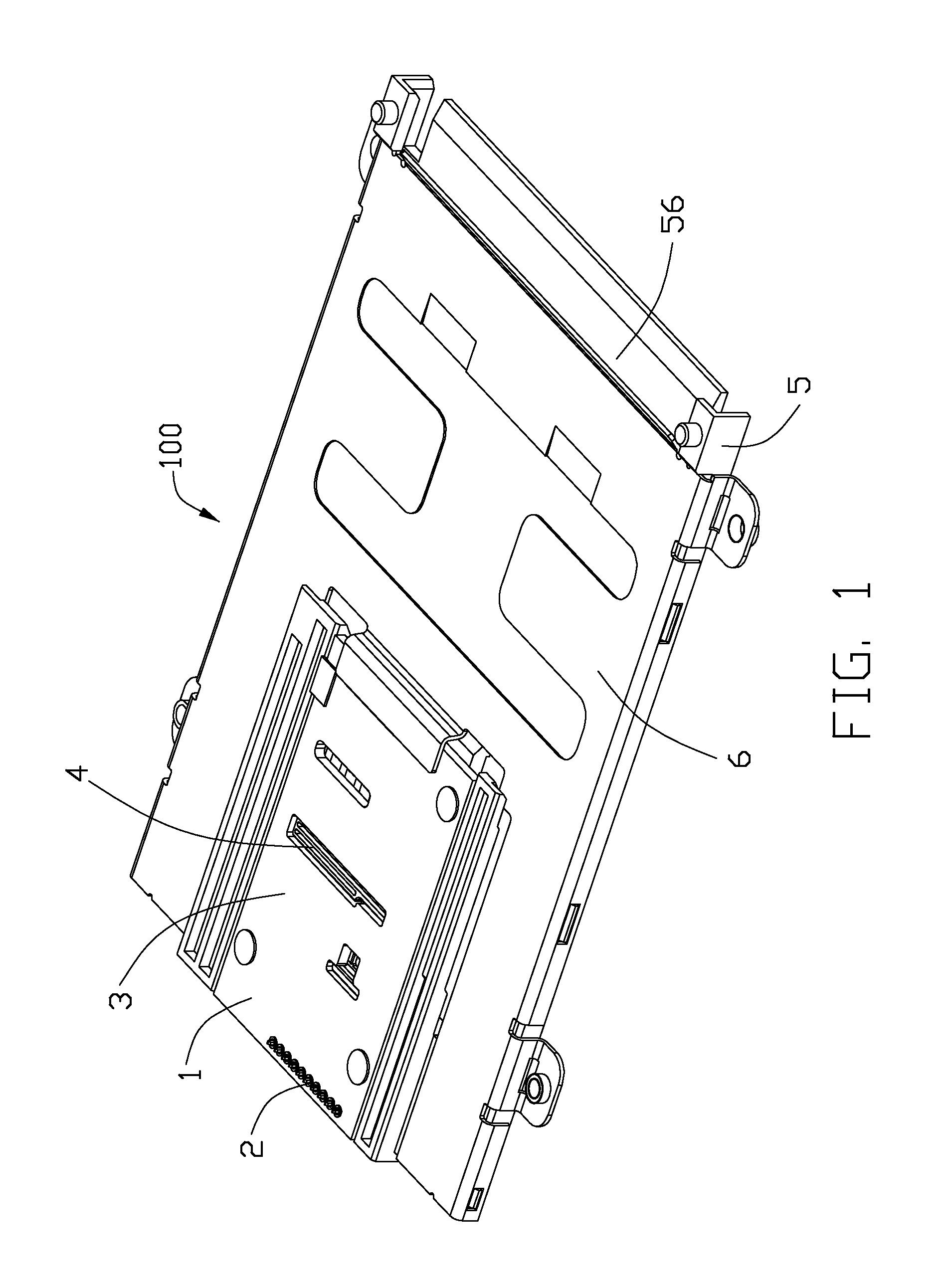
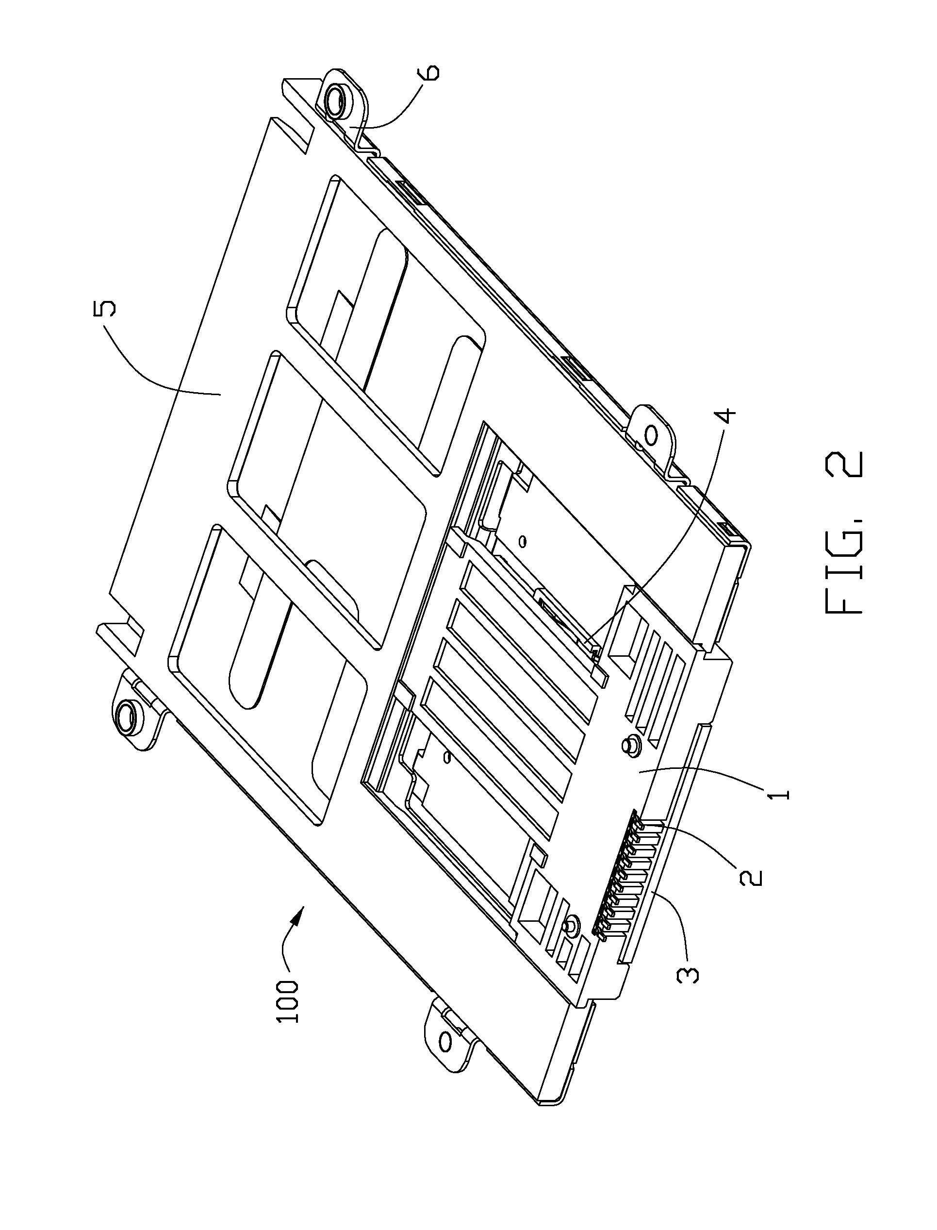
[0017]Referring to FIGS. 1-7, an electrical card connector 100 in accordance with the present invention is adapted for receiving a card 7 therein. The electrical card connector 100 comprises a first insulative housing 1, a plurality of first contacts 2 mounted to the first insulative housing 1, a printed circuit board 3 assembled to the first insulative housing 1, a contact module 4 mounted to the printed circuit board 3, a second insulative housing 5 engaged with the first insulative housing 1 and a metallic shell 6.

[0018]The first insulative housing 1 defines a bottom side 11, a top side 12 opposite to the bottom side 11. The bottom side 11 is located on a mother board (not shown) of a computer. The first insulative housing 1 has a base portion 13, a tongue portion 14 extending forwardly from a front side 131 of the base portion 13 and a pair of mounting arms 15 connected with lateral s...


PUM


Abstract

An electrical card connector (100) for receiving a card (7) with conductive traces (711) formed on a top side thereof includes a first insulative housing (1) having a base portion (11) and a tongue portion (12) extending forwardly from the base portion; a contact module (4) having an insulator (42) and a plurality of contacts (41) combined with an insulator; and a card receiving space (10) formed between the insulator and the tongue portion, with contacting portions (411) of the contacts extending into the card receiving space from an upper direction for mating with the conductive traces.

Description

BACKGROUND OF THE INVENTION[0001]1. Field of the Invention[0002]The present invention relates to an electrical card connector, and more particularly to an electrical card connector with improved contacts arrangement facilitating mating a card.[0003]2. Description of Related Art[0004]TW Pat. NO. M320206 issued on Oct. 1, 2007 discloses a smart card connector, and the small card connector includes an insulative housing, a contact module and a metallic shell. The insulative housing is mounted to a mother board, and the contact module is assembled to the insulative housing and the metallic shell mounted to the insulative housing. There is a card receiving space formed between the metallic shell and the insulative housing to accommodate a corresponding card. The contact module has a plurality of contacts mounted thereon, and each contact has a tail portion soldered to the mother board and a contacting portion extending into the card receiving space. The contacting portions of the contact...

Claims


Application Information

Patent Timeline
IPC IPC(8): H01R24/00
CPCH01R13/64H01R12/721
Inventor TUNG, CHANG-HSIENHSU, KUO-CHUNYU, HUNG-CHI
Owner HON HAI PRECISION IND CO LTD
Why Eureka
Try Eureka