Multi-part electrodes for a heater layer

a heater layer and electrode technology, applied in the direction of ohmic resistance heating, ohmic resistance heating details, electrical equipment, etc., can solve the problems of non-uniform heat transfer to the barrel, accelerated aging, and changeable contact pressure, etc., to achieve the effect of improving the contact arrangemen

Active Publication Date: 2016-08-16
XALOY INCORPORATED
View PDF21 Cites 0 Cited by
  • Summary
  • Abstract
  • Description
  • Claims
  • Application Information

AI Technical Summary

Benefits of technology

[0014]Accordingly, it is a primary object of the present invention to provide an improved contact arrangement between resistance heaters on plasticating barrels and their power supplies.
[0015]An additional object of the present invention is to provide an adequate electrical contact area for positive, robust and well-bonded electrical connections that can survive high temperatures and extreme thermal cycles such as those found in plasticating operations.
[0016]It is another object of the present invention to prevent surface oxidation of electrical contacts and resistance heater wires, especially the closely spaced wires constituting an electrode band of a wound-wire heater.

Problems solved by technology

Because of the high temperatures, severe duty cycles, and difficult environments in which plasticating barrels operate, there are many problems associated with the standard contact resistance heating of plasticating barrels.
However, the contact pressure can change with age and wear.
This produces variable heat transfer resistance between the contact resistance heaters and the barrel, and ultimately non-uniform heat transfer to the barrel.
Hot-spots also occur, and further accelerate aging, and eventually may lead to failure of the heating element.
Also, non-uniform heating can negatively impact the plasticating process and the quality of the plastic parts, which are produced from the plasticating process.
It should be noted that the manufacture of resistance wire-ceramic heater layers formed on plasticating barrels can be problematic since it is often difficult to maintain the proper level of tension on the wires during the manufacturing process.
However, there are certain difficulties inherent to this design so that this design can be improved upon.
The mechanical arrangement of an electrode on a cylindrical plasticating barrel makes external connections difficult under the best of circumstances, and under extreme conditions very problematical.
In particular, loosening of the external connections can result in localized high resistances, resulting in localized over-heating, and eventually failure of the electrical connection.
In particular, the subject thermal spraying operation is expensive and time-consuming.

Method used


Image

  • Multi-part electrodes for a heater layer
  • Multi-part electrodes for a heater layer
  • Multi-part electrodes for a heater layer

Examples


Embodiment Construction

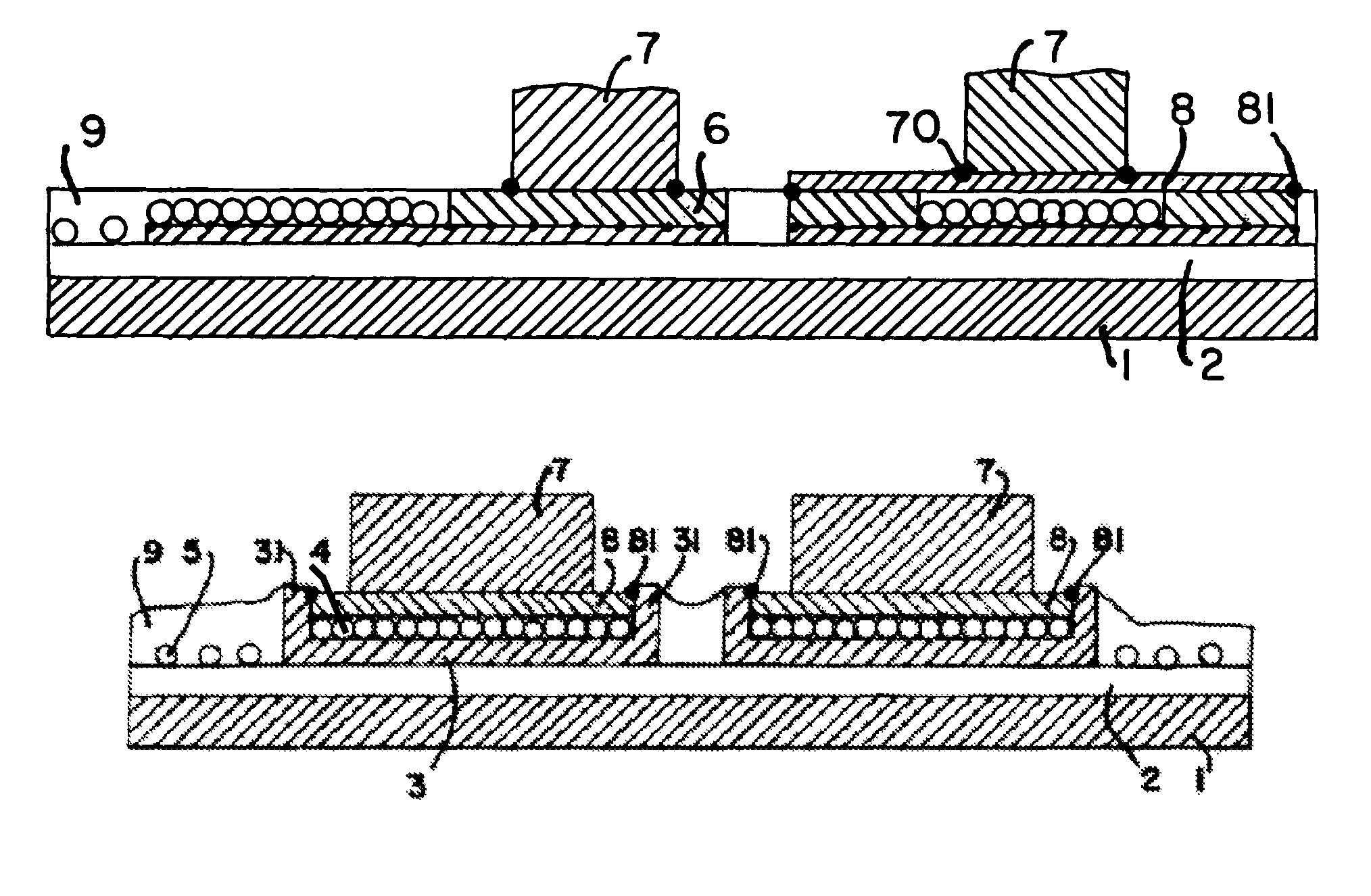
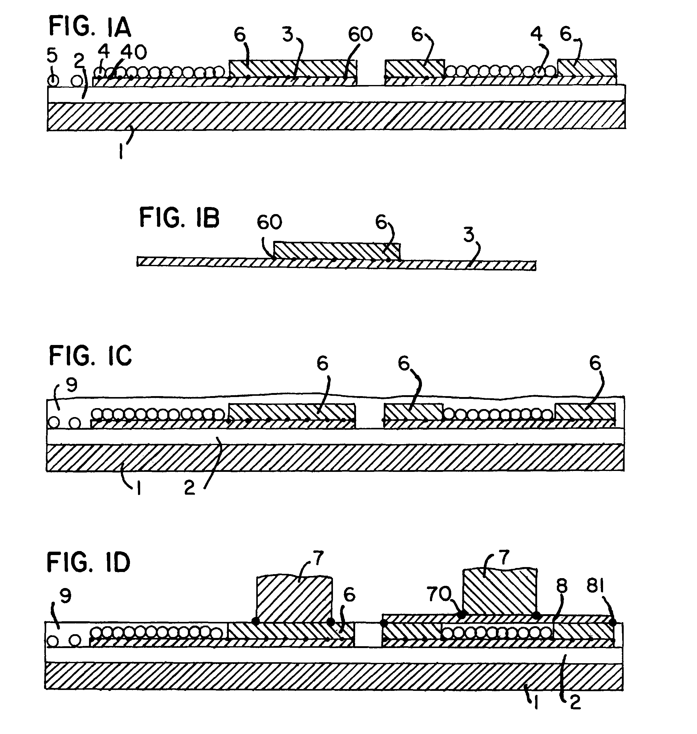
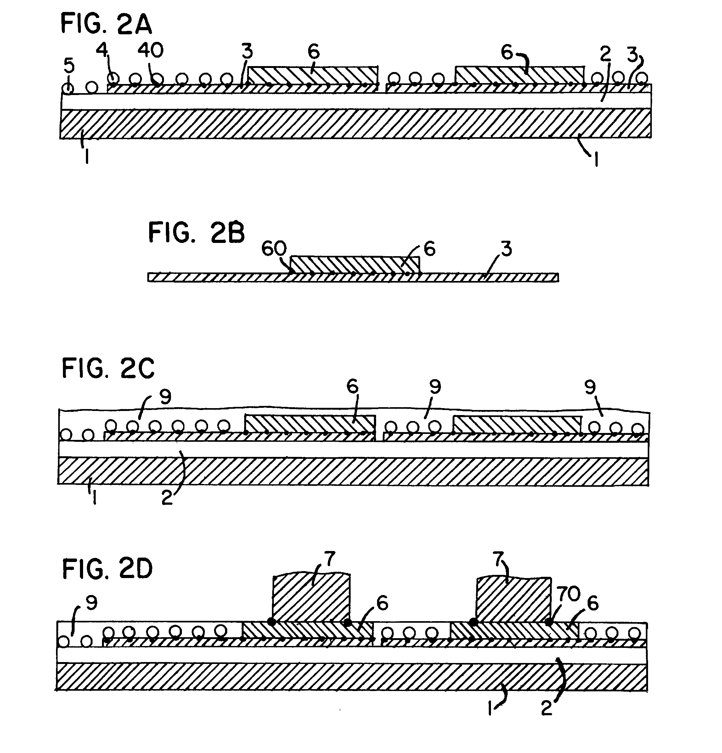
[0047]The present invention is directed to multi-part electrode structures, for connecting an external power source (not shown) to wound-wire contact resistance heater 5 arranged over a lower ceramic insulation layer 2, covering a plasticating barrel constituted by cylinder 1.

[0048]Part of the electrode structure is a band 4 composed of closely spaced wire windings (each attached at one end of heater windings 5) to form the electrode band. The closely spaced windings of electrode band 4 are formed over a lower plate 3 of a multi-part electrode structure. Upper electrode plates 6 are placed on the lower electrode plates 3 adjacent to the closely wound electrode band 4, as depicted in the drawings.

[0049]As depicted in FIG. 1(a), two upper electrode plates 6 on lower electrode plate 3 can flank or straddle a closely wound electrode band 4. The upper electrode plates 6, when exposed, can serve as anchor points for external connector structures 7, such as studs, nuts, or the like. Extern...


PUM

PropertyMeasurementUnit
sizeaaaaaaaaaa
sizeaaaaaaaaaa
areaaaaaaaaaaa

Abstract

The present invention is directed to an electrode structure which is most applicable for plasticating barrels having wound, wire resistance heaters. Electrode structure includes at least one lower electrode plate and an upper electrode plate. A closely wound electrode band connected to the wound wire resistance heater is formed over the lower electrode plate to assure maximum electrical, and thus, thermal transfer. An upper ceramic layer is formed over the electrode band and wound wire resistance heaters. This upper ceramic layer can be ground down to accommodate the addition of an external plate on top of the upper electrode plate.

Description

PRIORITY INFORMATION[0001]The present invention claims priority to U.S. Provisional Applications Nos. 61 / 521,087, filed on Aug. 8, 2011, and 61 / 515,522, filed on Aug. 5, 2011, and makes reference to same in their entireties.FIELD OF INVENTION[0002]The present invention relates generally to the heating of plasticating barrels. In particular, the present invention is directed to contact or electrode structures for connecting resistance heating elements, such as a wire-ceramic heating layer, formed on plasticating barrels, to external power sources, and other devices.BACKGROUND OF THE INVENTION[0003]The raw materials, such as resin pellets, processed in plasticating barrels are heated by a variety of different methods to obtain a near-liquid or plasticated state. For example, raw materials can be ground and heated before entering the barrel / screw combination for further heating to obtain plastication.[0004]Even when this is done, the primary method of heating the raw material (such as ...

Claims


Application Information

Patent Timeline
Patent Type & Authority Patents(United States)
IPC IPC(8): H05B1/00H05B3/08H05K13/00
CPCH05B3/08H05B1/00H05K13/00Y10T29/49083
Inventor HYLLBERG, BRUCE E.TAYLOR, BRUCE F.
Owner XALOY INCORPORATED
Why Eureka
Try Eureka