Aircraft Having a Variable Geometry

a variable geometry and aircraft technology, applied in the field of aircraft having a variable geometry, can solve the problems of reducing agility, difficult to design suitable pivoting kinematics for a predefined wing area, and disadvantages of known aircrafts with variable geometry, so as to reduce aerodynamic forces, reduce aerodynamic forces, and reduce aerodynamic forces.

Active Publication Date: 2012-04-12
AIRBUS DEFENCE & SPACE
View PDF23 Cites 31 Cited by
  • Summary
  • Abstract
  • Description
  • Claims
  • Application Information

AI Technical Summary

Benefits of technology

[0042]According to a second aspect of the method for changing the geometry of the aircraft, which can also be combined with the first aspect, it is provided that the change of the geometry (by pivoting the outer wing sections) during the flight takes place in a flight condition with significantly reduced aerodynamic forces, in particular, for example, at the outer wing sections. This reduces the risk that by initiating the pivoting movement, although the resulting changes of the aerodynamic conditions with respect to flight stability are too drastic. In case of an aerodynamic pivoting drive, this measure prevents the pivoting movement from being performed too fast. In case that, alternatively or additionally, a separate drive (e.g., electromotive drive) or the mentioned auxiliary pivoting mechanism is employed for initiating the pivoting movement, this results advantageously in low requirements with respect to the performance of such a drive or such a mechanism.
[0043]The term “significantly reduced aerodynamic forces” covers in particular such forces that effect a torque acting on the outer wing section with respect to the pivot axes and which is not more than 50%, preferably not more than 25% of the torque which results from a normal straight and level flight (cruise flight).

Problems solved by technology

However, the known aircrafts with variable geometry also have disadvantages.
However, such wings reduce the agility due to the relative high moment of inertia about the longitudinal axis of the aircraft.
Moreover, slim wings make it difficult to design suitable pivoting kinematics for a predefined wing area.
In case of outer wing sections that can be pivoted upwardly, ascending forces have to be considered which, without such a locking mechanism, could cause undesired upward pivoting of the outer wing sections.
In this respect, an asymmetric profile which, for example, provides an uplift in the non-pivoted state, would often be disadvantageous due to a descending force in the pivoted state.
This reduces the risk that by initiating the pivoting movement, although the resulting changes of the aerodynamic conditions with respect to flight stability are too drastic.

Method used


Image

  • Aircraft Having a Variable Geometry
  • Aircraft Having a Variable Geometry
  • Aircraft Having a Variable Geometry

Examples


Embodiment Construction

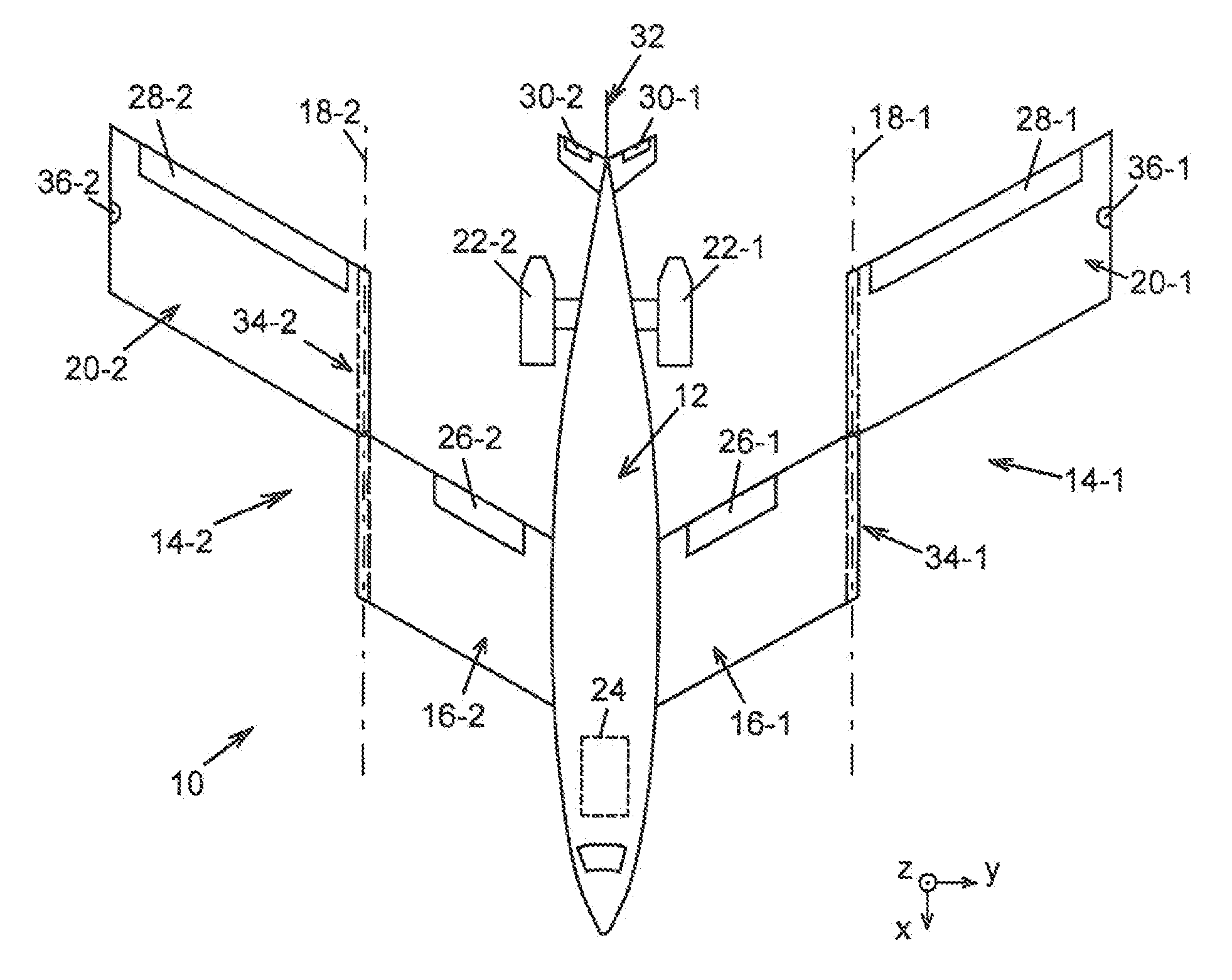
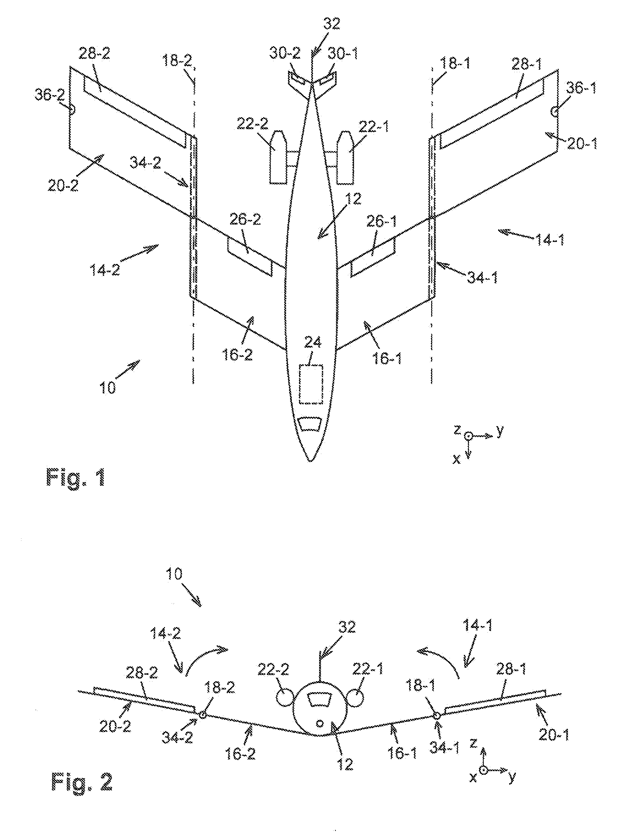
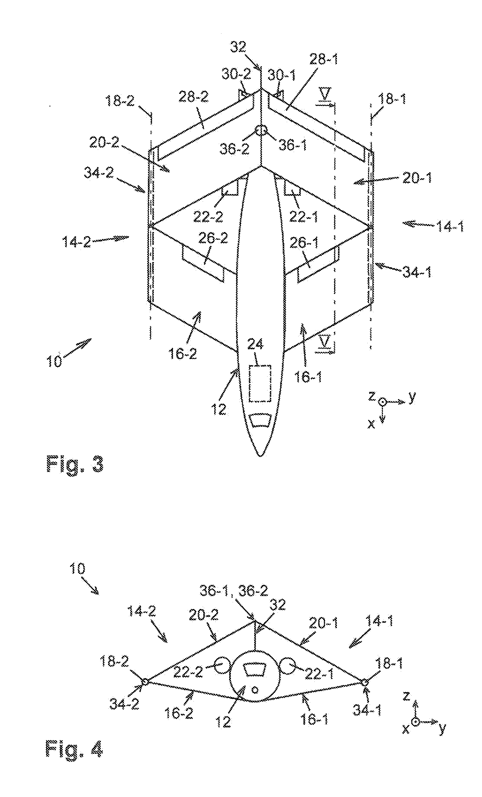
[0051]FIGS. 1 and 2 show an aircraft 10, comprising a fuselage 12 with a pair of wings 14-1 and 14-2 projecting therefrom on both sides in the transverse direction y, each of which wings has an “inner wing section”16-1 or 16-2, respectively, arranged stationarily with respect to the fuselage 12 and an “outer wing section”20-1 or 20-2, respectively, arranged adjacent thereto which, with respect to the inner wing section 16-1 or 16-2, respectively, can be pivoted about the pivot axis 18-1 or 18-2, respectively, which is oriented in the longitudinal direction (flight direction) x.

[0052]The reference numbers of components which are provided twice (to the left and right of the center of the fuselage) in the exemplary embodiment but are analog with respect to their effect such as, e.g., the wings 14-1 and 14-2, are numbered consecutively (in each case complemented by a hyphen and the number “1” or “2”). Reference to individual components of such components or the entirety of such componen...


PUM


Abstract

An aircraft having a variable geometry for adapting the flight characteristics to different flight situations includes a fuselage with a pair of wings projecting on both sides of the fuselage in the transverse direction (y), each of which wings has an inner wing section arranged stationarily with respect to the fuselage and an outer wing section adjacent thereto and pivotable about a pivot axis. The pivot axis is oriented in a direction deviating from the longitudinal direction (x) of the aircraft by a maximum of 40°.

Description

CROSS-REFERENCE TO RELATED APPLICATIONS[0001]The present application claims priority under 35 U.S.C. §119 to German Patent Application No. 10 2010 048 139.4, filed Oct. 11, 2010, the entire disclosure of which is expressly incorporated by reference.BACKGROUND AND SUMMARY OF THE INVENTION[0002]The present invention relates to an aircraft having a variable geometry for adapting the flight characteristics and, further, to the use of such an aircraft or a method for changing the geometry of the aircraft during the flight.[0003]Airplanes with variable geometry are sometimes referred to as “swing-wing aircrafts” (e.g. “Grunmann F-14 Tomcat”, “Mikojan-Gurewitsch MiG-23 and MiG-27” etc.). These known aircrafts comprise a fuselage with a pair of wings projecting therefrom in the transverse direction. Each of the wings has an inner wing section arranged stationarily with respect to the fuselage and an outer wing section adjacent thereto and pivotable about a pivot axis. The pivot axis is subs...

Claims


Application Information

Patent Timeline
Patent Type & Authority Applications(United States)
IPC IPC(8): B64C3/42
CPCB64C3/10B64C39/068B64C3/42B64C3/16B64C3/546B64C3/56Y02T50/10
Inventor SEIFERT, JOST
Owner AIRBUS DEFENCE & SPACE
Why Eureka
Try Eureka