Base station and method of controlling the same

Active Publication Date: 2012-04-19
KYOCERA CORP
View PDF4 Cites 11 Cited by
  • Summary
  • Abstract
  • Description
  • Claims
  • Application Information

AI Technical Summary

Benefits of technology

[0021]According to the present invention, it is possible to provide the base station capable of maintaining a communication quality of the communication t

Problems solved by technology

Nonetheless, there still are areas, such as inside houses and buildings and at bad locations behind mountains or buildings, providing no service or unstable communication as unable to receive radio waves, or due to weak radio waves, from existing usual base stations (that is, radio base stations connected to the mobile com

Method used


Image

  • Base station and method of controlling the same
  • Base station and method of controlling the same
  • Base station and method of controlling the same

Examples


first embodiment

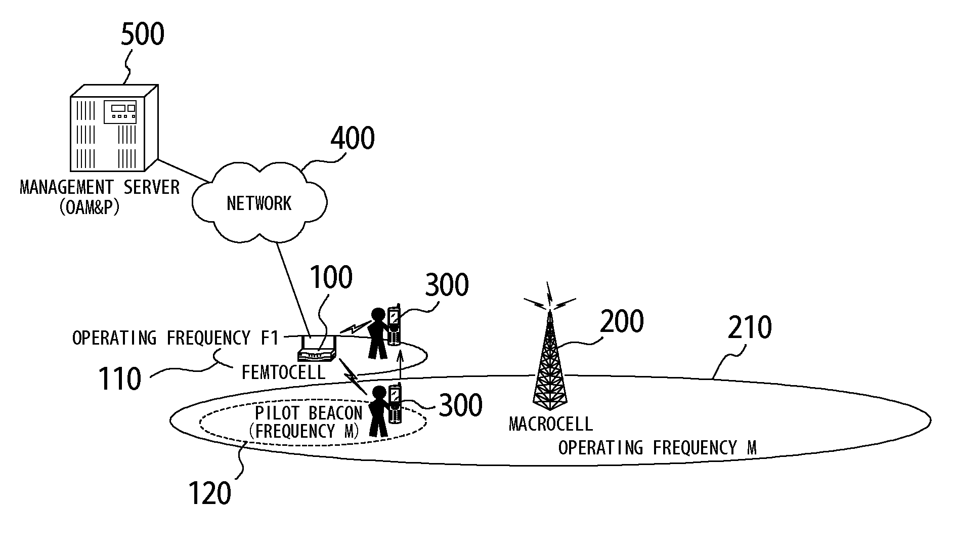
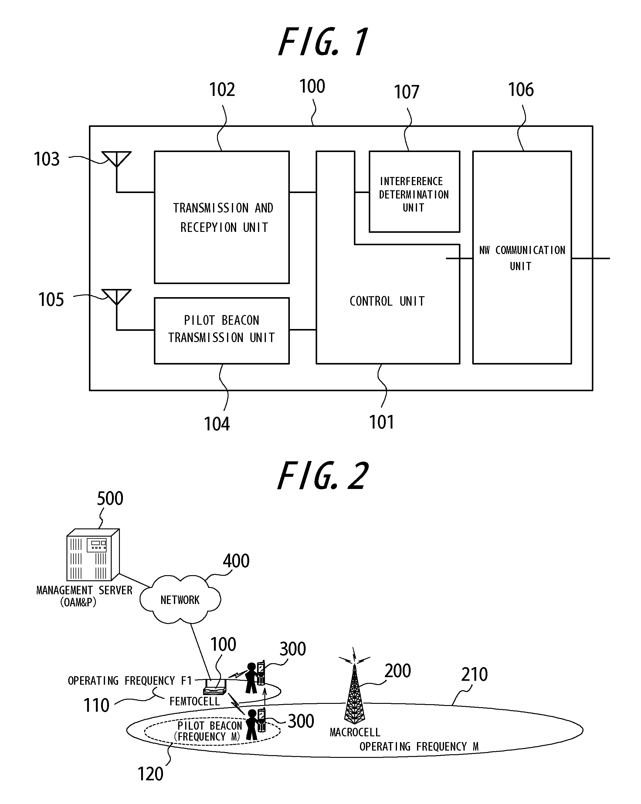
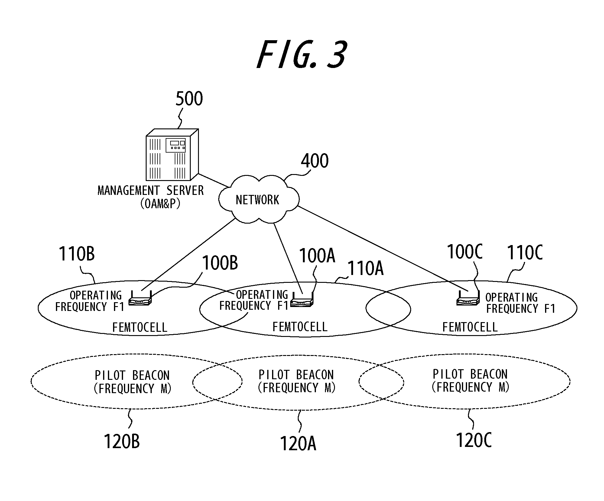
[0045]Next, a change of the operating frequency of the femtocell is described according to a first embodiment of the present invention. FIG. 3 is a diagram illustrating a state in which the radio waves are interfered by the femtocell closely installed. The femtocell 100 may be installed at any position connectable to the public line such as the broadband network. As shown in FIG. 3, accordingly, if femtocells 100A, 100B and 100C are installed close to one another, communication available areas 110A, 110B and 110C overlap one another, which is likely to cause interference with the radio waves.

[0046]Next, FIG. 4 is a diagram illustrating a state in which the operating frequency of the femtocell and the frequency of the pilot beacon are changed. If it is determined by the interference determination unit 107 of the femtocell 100A that the radio wave is interfered, due to installation of the femtocell 100 at a position where it is likely to interfere the radio wave as shown in FIG. 3, th...

second embodiment

[0059]Next, change of the operating frequency of the femtocell will be described according to the second embodiment of the present invention. FIG. 3 is the diagram illustrating the state in which the radio waves are interfered by the femtocell closely installed. The femtocell 100 may be installed at any position connectable to the public line such as the broadband network. As shown in FIG. 3, accordingly, if the femtocells 100A, 100B and 100C are installed close to one another, the communicable areas 110A, 110B and 110C thereof overlap one another, which is likely to cause interference with the radio waves.

[0060]Next, FIG. 8 is a diagram illustrating a state in which the frequency of the pilot beacon is changed. If it is determined by the interference determination unit 107 of the femtocell 100A that the radio waves are interfered due to installation of the femtocell 100 at a position where it is likely to cause interference as shown in FIG. 3, the femtocell 100A reports interferenc...


PUM


Abstract

Provided is a base station capable of maintaining a communication quality of a communication terminal (mobile station) having registered its position with the base station itself, even if an operating frequency is changed. According to the present invention, the base station includes a transmission and reception unit 102 configured to transmit and receive signals at the operating frequency for communication with the communication terminal, a pilot beacon transmission unit 104 configured to transmit a pilot beacon to a communication terminal, in communication with another base station, at an operating frequency of the another base station in order to allow the communication terminal to detect the operating frequency of the base station itself, and a control unit 101, if changing the operating frequency of the transmission and reception unit 102, configured to control the pilot beacon transmission unit 104 to change the frequency of the pilot beacon to transmit therefrom to the operating frequency of the transmission and reception unit 103 before changed and transmit the pilot beacon at this frequency.

Description

CROSS REFERENCE TO RELATED APPLICATIONS[0001]This application claims priority to and the benefit of Japanese Patent Application No.2009-151878 (filed on Jun. 26, 2009) and Japanese Patent Application No.2009-196278 (filed on Aug. 27, 2009), the entire contents of which are incorporated herein by reference.TECHNICAL FIELD[0002]The present invention relates to base stations, and more specifically, to base stations connected to mobile communication networks and methods of controlling the base stations.BACKGROUND ART[0003]In late years, mobile communication devices, particularly mobile phones, have been rapidly widespread and service areas thereof cover most of Japan. Nonetheless, there still are areas, such as inside houses and buildings and at bad locations behind mountains or buildings, providing no service or unstable communication as unable to receive radio waves, or due to weak radio waves, from existing usual base stations (that is, radio base stations connected to the mobile com...

Claims


Application Information

Patent Timeline
IPC IPC(8): H04W4/00
CPCH04W72/042H04W84/045H04W72/082H04W72/541H04W72/23
Inventor HIDAKA, HIROYUKI
Owner KYOCERA CORP
Why Eureka
Try Eureka