Base station apparatus, terminal apparatus, and communication method therefor

a technology of base station and terminal, which is applied in the direction of electrical equipment, wireless communication, connection management, etc., can solve the problems of increasing the ratio of overhead such as control information or the like, and shortening the time from transmission data occurrence to transmission

Active Publication Date: 2019-05-09
SHARP KK
View PDF0 Cites 7 Cited by
  • Summary
  • Abstract
  • Description
  • Claims
  • Application Information

AI Technical Summary

Benefits of technology

[0022]According to the present invention, in a case that uplink data transmission based on OMA and uplink data transmission based on NOMA coexist in a cell in which many terminal apparatuses present, a prescribed communication quality for the uplink data can be maintained.

Problems solved by technology

As a result, in a case that transmission data with small size increase, a ratio of overhead such as the control information or the like relatively increases.
Furthermore, the contention based radio communication technique can shorten time from transmission data occurrence to the transmission.

Method used


Image

  • Base station apparatus, terminal apparatus, and communication method therefor
  • Base station apparatus, terminal apparatus, and communication method therefor
  • Base station apparatus, terminal apparatus, and communication method therefor

Examples


first embodiment

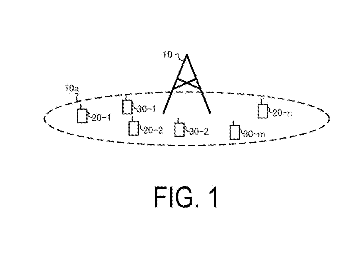
[0037]A communication system according to the present embodiment includes a base station apparatus (a transmission device, cells, small cells, serving cells, a transmission point, a group of transmit antennas, a group of transmit antenna ports, component carriers, eNodeB, Home eNodeB) and terminal apparatuses (a terminal, a mobile terminal, a reception point, a reception terminal, a reception device, a group of receive antennas, a group of receive antenna ports, UE). The communication system is not limited to data communication between a terminal apparatus and base station apparatus with human intervention, can also be applied to a form of data communication, which does not require the human intervention, such as Machine Type Communication (MTC), Machine-to-Machine Communication (M2M communication), Internet of Things (IoT) communication, Narrow Band-IoT (NB-IoT), or the like (hereinafter, referred to as MTC). In this case, the terminal apparatus is an MTC terminal. The communicatio...

second embodiment

[0198]A communication system according to the present embodiment is configured of the base station apparatus 10 and the terminal apparatuses 20 and 30 described with reference to FIG. 1, FIG. 10 to FIG. 12. Hereinafter, differences / additional points with respect to the first embodiment will be mainly described.

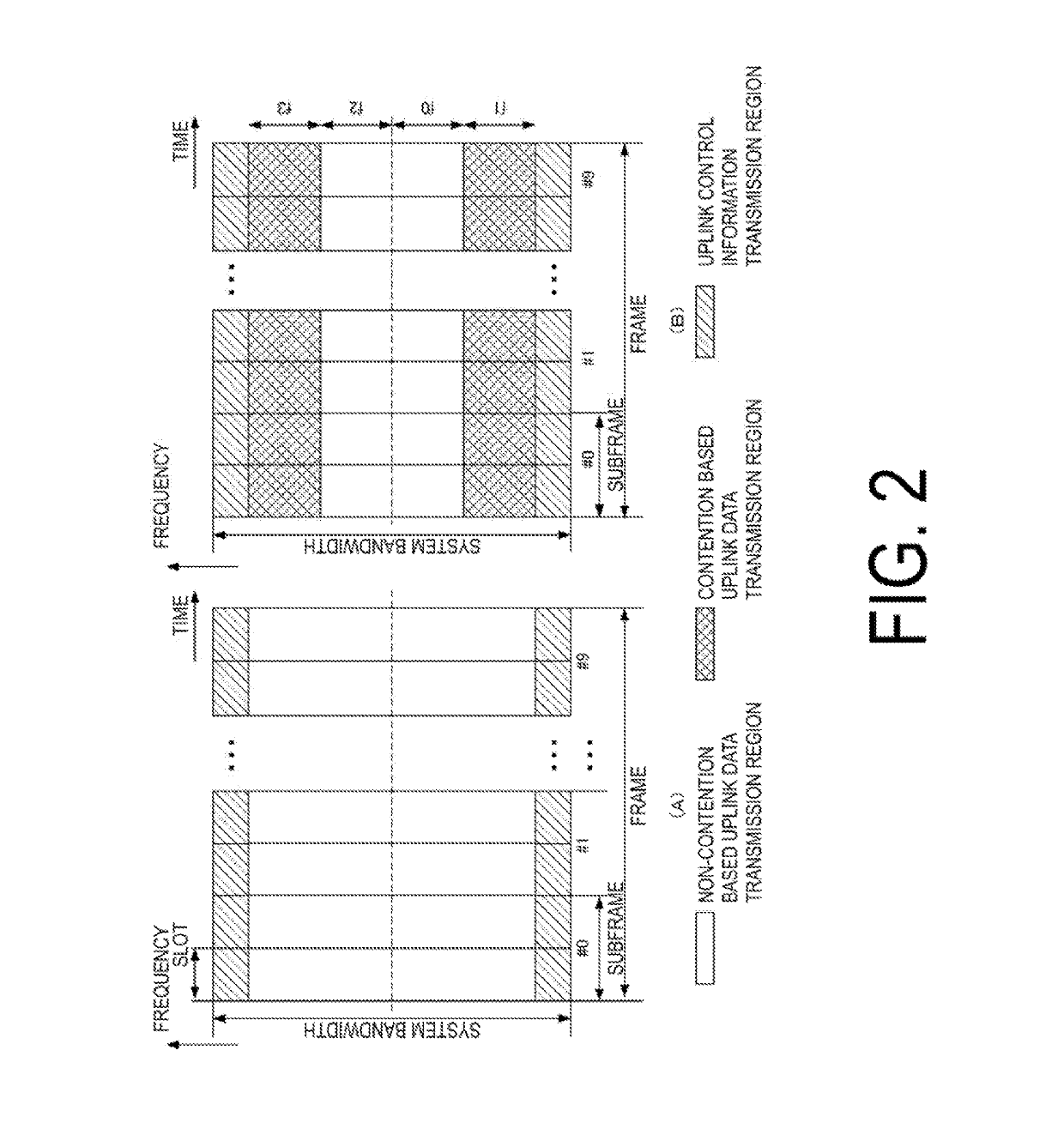
[0199]FIG. 13 is a diagram illustrating an example of the uplink radio frame format according to the present embodiment. In FIG. 13, a white portion is a region (resource) in which the non-contention based uplink data channel (for example, PUSCH) is transmitted. The shaded portion is a region in which the contention based uplink data channel is transmitted. A rightward-ascending diagonal line portion is a region in which the uplink control channel (for example, PUCCH) is transmitted.

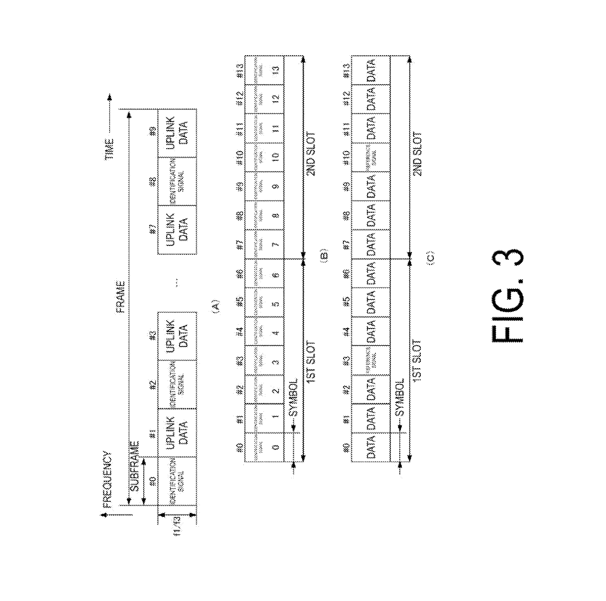
[0200]To the contention based uplink data transmission region (shaded portion), the subframe format illustrated in FIGS. 3A to 3C can be applied. Resources for allocating the PRACH and the referenc...


PUM


Abstract

Provided are a base station apparatus, a terminal apparatus, and a communication method, in a case that uplink data transmission based on orthogonal multiple access and uplink data transmission based on non-orthogonal multiple access coexist in a cell in which many terminal apparatuses present, capable of maintaining a prescribed communication quality for the uplink data. The base station apparatus for communicating with a terminal apparatus configured to support contention based access and non-contention based access transmits, in a case that an uplink data channel received in a non-contention based manner occurs in a subframe including the contention based access region, a contention based transmission configuration change notification with respect to a subframe configured to receive the uplink data channel.

Description

TECHNICAL FIELD[0001]The present invention relates to a base station apparatus, a terminal apparatus, and a communication method therefor.BACKGROUND ART[0002]In a communication system, such as the Long Term Evolution (LTE), the LTE-Advanced (LTE-A), or the like, specified in the Third Generation Partnership Project (3GPP), a terminal apparatus (User Equipment (UE)) transmits, in a case of including transmission data in an uplink buffer, a Scheduling Request (SR), a Buffer Status Report (BSR), or the like to a base station apparatus (evolved Node B (eNodeB)). Thereafter, the terminal apparatus transmits data by a prescribed radio resource in a case of receiving control information of an uplink transmission grant (UL Grant) from the base station apparatus, based on an uplink transmission parameter included in the UL Grant. In this manner, the base station apparatus controls radio resources for all the uplink data transmissions (data transmission from the terminal apparatus to the base...

Claims


Application Information

Patent Timeline
Patent Type & Authority Applications(United States)
IPC IPC(8): H04W72/12H04W76/27H04W72/14
CPCH04W72/1284H04W76/27H04W72/14H04W72/12H04W74/02H04W74/08H04W72/23H04W72/21
Inventor YOSHIMOTO, TAKASHIGOTO, JUNGONAKAMURA, OSAMUYAMADA, RYOTAHAMAGUCHI, YASUHIRO
Owner SHARP KK
Why Eureka
Try Eureka