Monitoring and control module

a communication device and monitoring module technology, applied in the field of voice encoded communications, can solve the problems of reducing the profitability of providing traditional long distance telephone service, limiting competition, and poor utilization of available bandwidth on active voice trunks, and achieve the effect of improving communication quality

Inactive Publication Date: 2008-08-26
TIERRA TELECOM
View PDF2 Cites 8 Cited by
  • Summary
  • Abstract
  • Description
  • Claims
  • Application Information

AI Technical Summary

Benefits of technology

[0017]The invention described herein overcomes the drawbacks in the prior art by providing a method and apparatus to facilitate the transmission of telecommunications over a packet-switched network, packet-based transmission system, or other medium separate from the voice telephone network. One advantage of the invention is reduced cost of telecommunications due to use of an Internet packet-switched network. Another advantage of the invention is monitoring of optimal routing paths prior to call set-up. Another advantage of the invention comprises monitoring of the communication session in real time for quality. Another advantage of the invention comprises re-routing of the communication session to an alternate path to maintain communication quality. Yet another advantage of the invention comprises use of least-cost-routing analysis to determine path selection within the computer network. In one configuration, least-cost-routing determines the path that results in the lowest charges being assigned to the call from completion over aspects of the public switch telephone network (PSTN).
[0018]In one configuration two or more Interfaces are located at various desired locations throughout the world. The Interfaces are enabled to communicate over a communication medium, in one embodiment the Internet. One or more Monitoring and Routing systems (M / R system) may optionally interact with the two or more Interfaces to serve as a central manager or network operations center.
[0019]The M / R system communicates with the Interfaces to evaluate the communication path characteristics between the various Interfaces. In one configuration the evaluation is based on feedback from the Interfaces regarding test packets or ping packets sent between the Interfaces to determine path characteristics and an analysis of any type of packet sent between Interfaces. The M / R system's evaluation determines the optimal routing between Interfaces.
[0020]In one configuration the Interface comprises a combination of hardware and software having systems that communicate and interact with a telephone network and having further systems to communicate and interact with a computer network, such as the Internet. In one configuration the M / R system comprises a combination of hardware and software configured to communicate and interact with a computer network.
[0021]In operation the Interface receives calls or other requests for services from another communication network, such as the PSTN. Upon receipt, the incoming call provides destination information and call data. The Interfaces, in conjunction with the M / R system, process the incoming call and utilize the destination information to determine a destination Interface. Optional variable compression may be performed on the call. The Interface converts the call data to packets having header information determined by the call destination. Thereafter, the Interface transmits the call in packet form on a computer network for receipt by a destination Interface.
[0022]At the destination Interface, the Interface receives the packets and re-constructs the call from packet form for communication back on the telecommunication network so the call may be delivered to the call destination.

Problems solved by technology

At the same time, competition between long distance carriers has increased thereby reducing profitability in providing traditional long distance telephone service.
This further limits competition.
One drawback of the present telecommunication system operating under the SS7 standard is the poor utilization of available bandwidth on an active voice trunk.
Such a method of operation poorly utilizes voice channels, voice being a data stream in which long periods of silence occur and only requires limited bandwidth and which is greatly compressible.
Another drawback of prior art systems is the high cost of adding additional resources.
To add additional voice channels additional cables must be installed and expensive equipment utilized to facilitate communication over each of the one or more newly installed cables.
These costs can be substantial.
A further disadvantage to such prior art systems is their congregation in the control of a few large and powerful corporations.
However, these long distance carriers are often organizations without actual long distance capability and hence must purchase long distance access in bulk from one of the large long distance service providers to complete calls that cross a LATA boundary.
Because the large long distance service providers control the market, the small to mid-sized carrier may be forced to pay higher rates than the large long distance service providers.
This is yet another factor that limits competition.
Yet another drawback to the prior art system of providing long distance communication service is one or more governmental fees that may be imposed as a result of governmental regulation.
While existing prior art systems could be expanded, such expanded systems would undesirably suffer from the drawbacks described above.
Most notably, prior art voice-over-IP systems provide unacceptable quality of communications because of data loss in packets progressing via the Internet and because of delays associated with transmission via the Internet.
As a result, prior art voice-over-IP is prohibitively expensive, inconvenient, and is not available in most locations due to the requirement for specialized equipment.

Method used


Image

  • Monitoring and control module
  • Monitoring and control module
  • Monitoring and control module

Examples


example environment

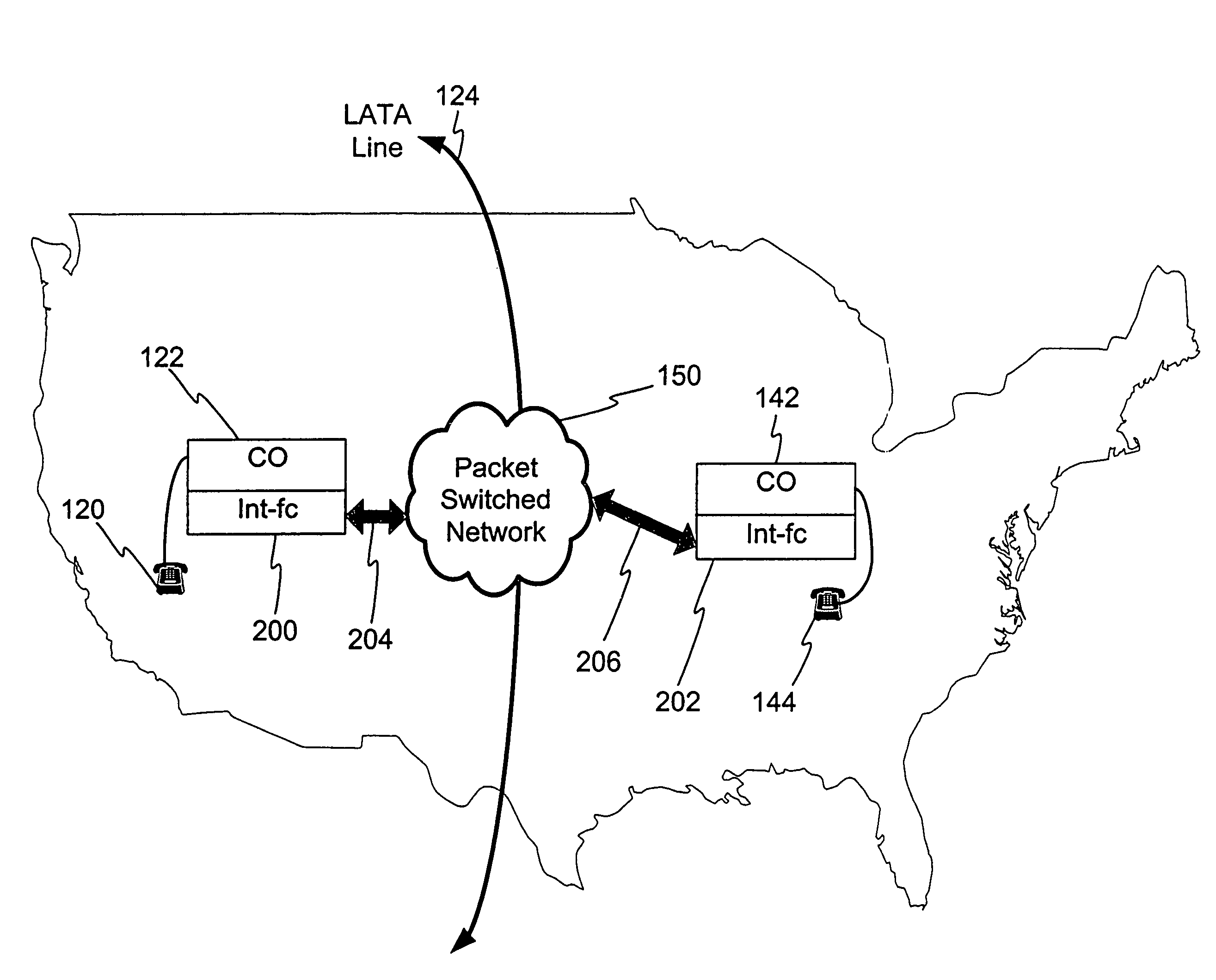
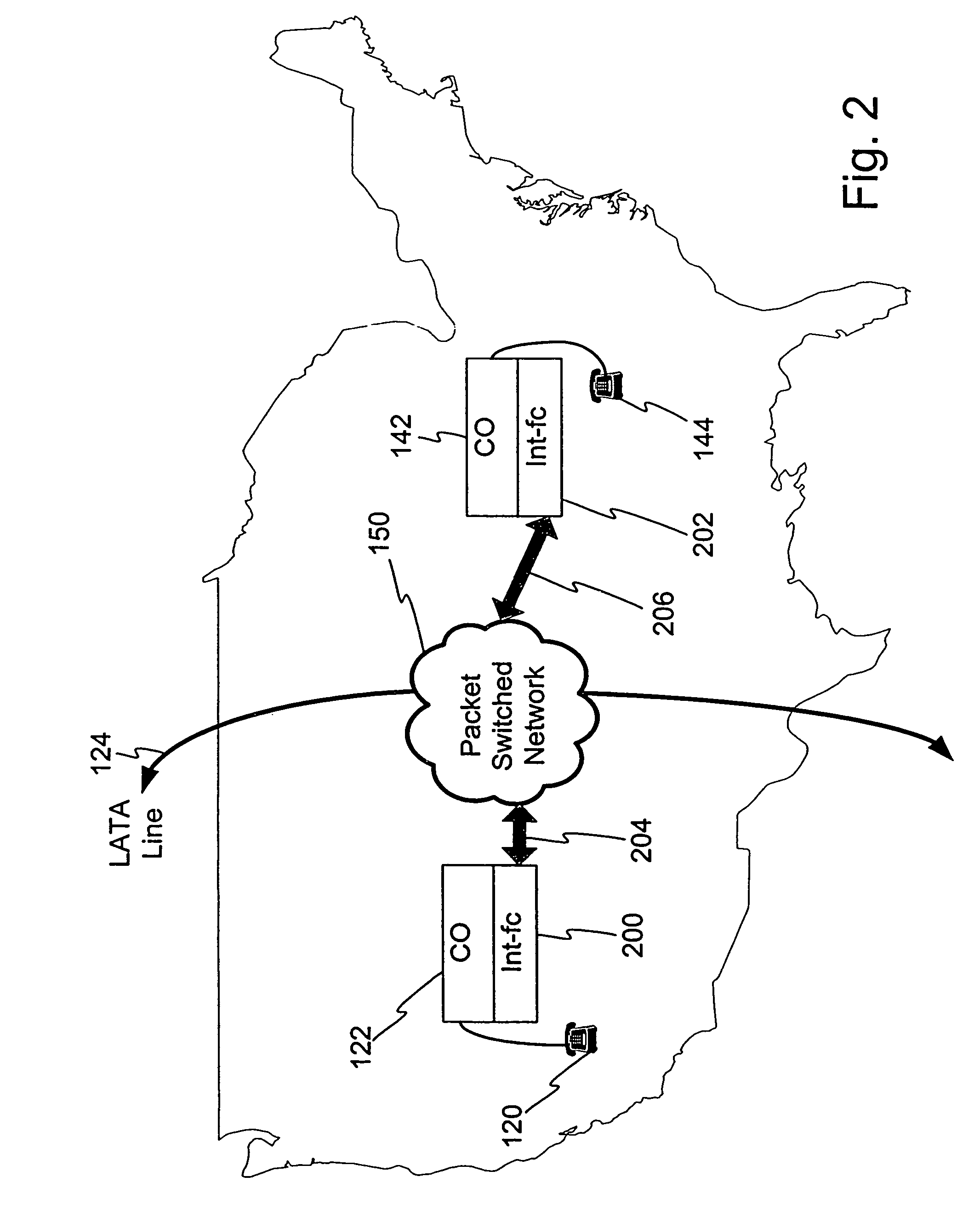
[0053]For purposes of understanding, the present invention is first described in an example environment well suited for use of the present invention. FIG. 2 illustrates an example environment of a telephone network. In comparison to FIG. 1, like elements are labeled with like reference numerals. As shown, a communication device, such as telephones 120, 144 connects to a central office 122, 142 via a local loop or any other communication medium. Co-located within each central office 122, 142 is the Interface 200, 202 (Voice / Packet Interface) of the present invention. The equipment of the central office 122, 142 responsible for receiving and routing the incoming call is configured in communication with the Interface 200, 202. Generally similar configurations exist in central office 122 and central office 142. As the configuration of the central office 122, 142 is generally understood by those of ordinary skill in the art, a detailed description is not provided herein.

[0054]Each of the...

example embodiments

[0055]FIG. 3 illustrates a block diagram of the present invention's linkage with existing systems of a telecommunication system wherein more than two Interfaces 200, 202, 220, 230 are enabled for operation. In comparison to FIG. 2, like elements are referenced with like reference numerals. As shown in this figure, the Interface 200 and Interface 202 are located remotely from central office 122, 142 and connected to each other by high speed and high capacity communication media 210, 204, 150, 206, 216. In one embodiment the communication capacity comprises T-1 capacity. In other embodiments the communication capacity or standard may comprise T-3, T-4, E-1, E-3, or OC-3 capacity. Various media can be utilized to carry this capacity including wireless, microwave, satellite link, and fiber optics.

[0056]Also shown in FIG. 3 is additional Interface 220 communicating with the Internet 150 via high speed and high capacity lines 212 and interfacing with a third central office 222.

[0057]Also ...


PUM


Abstract

A method and apparatus for monitoring and controlling one or more aspects of one or more communication devices. In one embodiment the communication device is configured to transmit and receive packets of data via a packet-switched network. In one configuration the monitoring and controlling is performed by a command and control system (C / C system) that is configured to operate in conjunction with a communication device. In one configuration the communication device comprises an Interface device configured to Interface a voice communication network with a packet switched network. The C / C system may be configured to monitor or control aspects of the communication device including temperature, cooling device operation, security, drive operation, power supply output and power supply routing, system re-boots, or any other aspect of device operation. In one configuration the C / C system Interfaces with a remote location via a communication link, such as a packet switched network. Monitoring and control of various systems can be achieved from the remote location.

Description

CROSS REFERENCE TO RELATED APPLICATIONS[0001]This application is a continuation of and claims priority from application Ser. No. 09 / 677,776, filed Oct. 3, 2000, now abandoned the contents of which are incorporated herein by reference.FIELD OF THE INVENTION[0002]The present invention relates generally to voice encoded communications and in particular to a method and apparatus for monitoring and controlling a communication device.BACKGROUND OF THE INVENTION[0003]The worldwide demand for communication capability continues to increase due the advancement of areas undeveloped previously and the growth and expansion of businesses in already established areas. Moreover, homes or offices previously equipped with a single telephone line are now more likely to install two or even three lines to facilitate simultaneous communication by individuals or devices within the home or office.[0004]At the same time, competition between long distance carriers has increased thereby reducing profitability...

Claims


Application Information

Patent Timeline
Patent Type & Authority Patents(United States)
IPC IPC(8): H04M11/00G06F15/173H04L12/56H04L12/64H04M7/00H04Q3/00
CPCH04L12/6418H04L45/04H04L45/124H04Q3/0087H04L65/80H04L45/22H04L2012/6443
Inventor HOST, LAWRENCE WILLIAM
Owner TIERRA TELECOM
Why Eureka
Try Eureka