Multi-mode receiver circuit for dealing with various modulation systems and signal formats

a multi-mode receiver and receiver circuit technology, applied in the field can solve the problems of high cost, large occupied volume, waste of power consumption of multi-mode receiver circuits, etc., and achieve the effects of reducing power consumption, simplifying processing, and preventing wasteful operation of demodulator or decoder

Inactive Publication Date: 2010-08-03
LAPIS SEMICON CO LTD
View PDF11 Cites 8 Cited by
  • Summary
  • Abstract
  • Description
  • Claims
  • Application Information

AI Technical Summary

Benefits of technology

[0017]It is an object of the present invention to provide a multi-mode receiver circuit that is capable of preventing wasteful demodulation and decoding operations to reduce power consumption, while maintaining intended communication quality.
[0020]According to the multi-mode receiver circuit of the present invention, the shared receiver receives a signal formed according to one of various modulation and communication systems to output a received signal. The signal intensity detector detects the electric power value, or absolute value of the amplitude, of the received signal to output a detected signal. The determiner compares the magnitude of the detected signal with a plurality of threshold voltages, and generates control signals to output the latter to switches. The switches are operated in response to the respective control signals fed to the switches so that the received signal is selectively fed to demodulators. The demodulators demodulate the received signal according to a receiving system corresponding to the modulation or transmission systems to output demodulated signals. Accordingly, even when a received signal is a modulated wave whose amplitude is small with noise involved thereon, the possibility of the input path of the modulated wave to the demodulator or decoder being conducted in error can be suppressed. This can prevent wasteful operation of the demodulator or decoder, so that a reduction in power consumption and simplification of the processing of results of demodulation and decoding can be achieved. Besides, the multi-mode receiver circuit of the present invention is capable of suppressing the outputting of demodulation or decoding results that would otherwise be degraded in communication quality, so that it can obtain demodulation or decoding results while maintaining intended communication quality.

Problems solved by technology

Because of this, analog circuits and radio-frequency circuits have relatively been increased in geometrical area and manufacturing cost.
Generally, high-frequency circuits are high in power consumption, large in occupied volume, and costly.
Because of this, it is undesirable that the multi-mode receiver circuit be provided with a plurality of high-frequency circuits dedicated to deal with respective modulation systems and signal formats.
That causes multi-mode receiver circuits to be complicated in processing such as comparison of digital signals.
Multi-mode receiver circuits therefore have difficulties in circuit scale being increased or processing delay being increased.
The QPSK demodulator or ASK demodulator, however, will output a demodulated signal without maintaining intended communication quality.
As a result, the two demodulators other than appropriate one will consume electric power wastefully.
However, since the demodulation process cannot produce intended demodulated signals, unnecessary demodulated signals will be output.
As with the aforementioned case, this can cause wasteful power consumption.
Accordingly, the power consumption of the determiner is considered to be increased.
A variation in power value or amplitude of a QPSK modulated wave is small, so that noise, when involved in the QPSK modulated wave, renders the configuration disclosed in the '829 publication to present a strong possibility that the modulation system of a received signal will be determined in error.
Such a possibility of the modulation system being determined in error will take place without regard to the magnitude of the electric power value, or absolute value of the amplitude, of a received signal.

Method used


Image

  • Multi-mode receiver circuit for dealing with various modulation systems and signal formats
  • Multi-mode receiver circuit for dealing with various modulation systems and signal formats
  • Multi-mode receiver circuit for dealing with various modulation systems and signal formats

Examples


Embodiment Construction

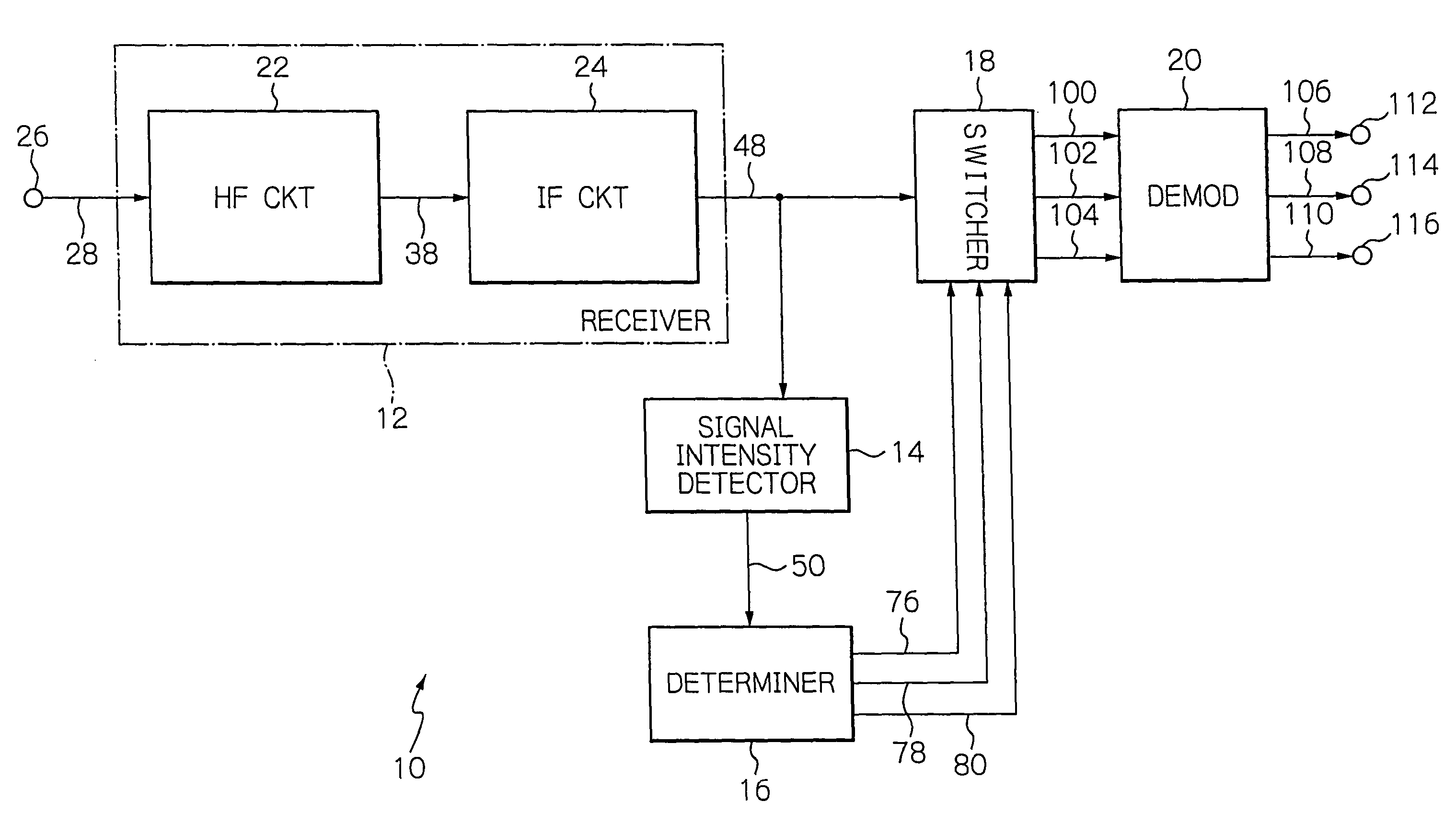
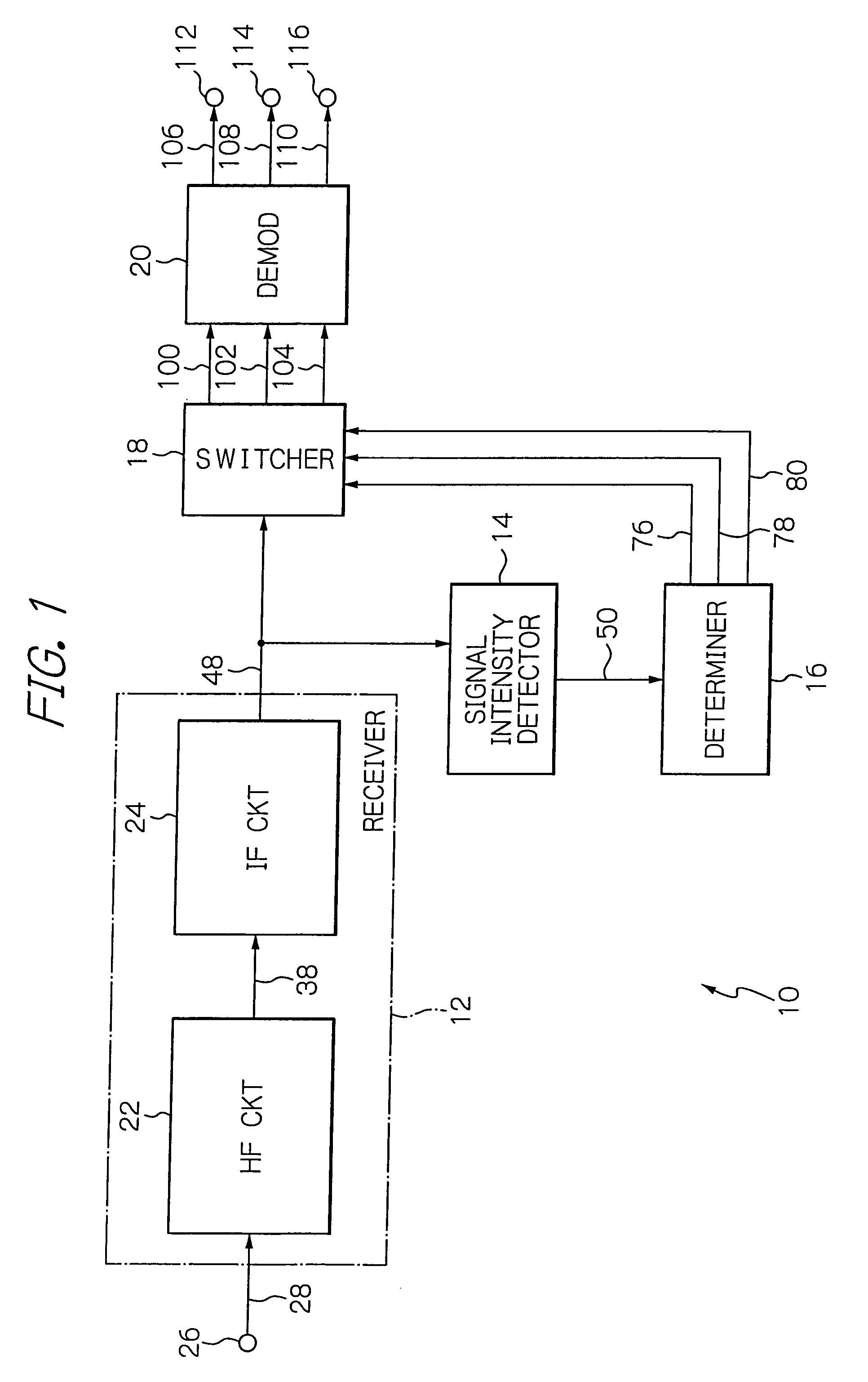
[0030]Preferred embodiments of a multi-mode receiver circuit according to the present invention will hereinafter be described in detail with reference to the accompanying drawings. Referring initially to FIG. 1, a first preferred embodiment of the multi-mode receiver circuit of the present invention is configured such that a shared receiver 12 receives a signal formed according to any one of various modulation or communication systems to output a received signal 48, a signal intensity detector 14 detects or determines the electric power value, or absolute value of the amplitude, of the received signal 48 to output a detected signal 50, a determiner 16 compares the magnitude of the detected signal 50 with a plurality of threshold voltages, not shown, and generates control signals 76, 78 and 80 to output the latter to a switcher 18, the switcher 18 is operated in response to the control signals 76, 78, and 80 fed to the switcher 18 so that the received signal 48 is responsively fed or...


PUM


Abstract

In a receiver set, a shared receiver receives a signal formed according to one of various modulation or communication systems to output a received signal. A signal intensity detector detects the electric power value, or absolute value of the amplitude, of the received signal to output a detected signal. A determiner compares the magnitude of the detected signal with threshold voltages, and generates control signals to output them to switches. The switches are operated in response to the respective control signals fed to the switches so that the received signal is selectively fed to demodulators. The demodulators demodulate the received signal according to a receiving system corresponding to the modulation or transmission systems to output demodulated signals.

Description

BACKGROUND OF THE INVENTION[0001]1. Field of the Invention[0002]The present invention relates to a multi-mode receiver circuit, and more particularly to a multi-mode receiver set for use in radio equipment which can deal with various kinds of modulation systems, signal formats, and coding systems.[0003]2. Description of the Background Art[0004]For integrated circuit (IC) applications, digital processing circuits fabricated on a semiconductor substrate have been reduced in horizontal and vertical dimensions to meet the high-density integration requirement. Because of this, analog circuits and radio-frequency circuits have relatively been increased in geometrical area and manufacturing cost. For that reason, multi-mode receiver circuits for use in radio equipment, which receive signals by adaptively switching modulation systems or signal formats which deal with a plurality of communication systems are designed to share an analog circuit and a high-frequency circuit with those systems ...

Claims


Application Information

Patent Timeline
Patent Type & Authority Patents(United States)
IPC IPC(8): H04L27/06H04B17/02H04B17/40
CPCH04L27/0012H04L27/0008H04L27/00H04L27/06H04L27/22H04L27/38
Inventor TAYA, TAKASHI
Owner LAPIS SEMICON CO LTD
Why Eureka
Try Eureka