Unlock instant, AI-driven research and patent intelligence for your innovation.
Connecting element for multilayer media, filter element, and method for connecting laminar media
Inactive Publication Date: 2012-04-26
MANN HUMMEL GMBH
View PDF5 Cites 10 Cited by
Summary
Abstract
Description
Claims
Application Information
AI Technical Summary
This helps you quickly interpret patents by identifying the three key elements:
Problems solved by technology
Method used
Benefits of technology
Benefits of technology
[0014]Moreover, at least two legs of the connecting element can be shaped such that an end section inserted between the two legs is secured by means of clamping action. This facilitates manufacture and, for example, thermal joining of the connecting element with the
Problems solved by technology
In particular in case of multilayer filter media, for example, several layers of thin nonwoven material that is impregnated or has special intermediate layers, it is difficult to prevent fraying at the edges that are resting against each
Method used
Image
Click on the blue label to locate the original text in one second.
Reading with bidirectional positioning of images and text.
Examples
Example
[0043]In FIG. 4, a second embodiment of a connecting element is illustrated. An E-shaped profile of the connecting element 1 is assumed. The connecting element 1 has a common edge 10 for the legs 1A, 1B, and 1C. A central leg 1A is provided that, for example, has a reduced thickness in comparison to the outer legs 1B and 1C. Into the intermediate spaces between the legs 1A and 1B a multilayer filter medium is inserted, respectively. In this context, a first filter medium 12 and a second filter medium 13 and a corresponding end section are illustrated. The two flat filter media each are manufactured of two layers 12A, 12B, 13A, 13B wherein between the respective layers, for example, active carbon particles 14 are deposited. In this way, the filter action and the absorption properties of the filter medium are improved.
[0044]Since in particular these multilayer filter media 12, 13 may fray at their terminal edges, the proposed connecting element 1 is particularly suitable. This is so b...
Example
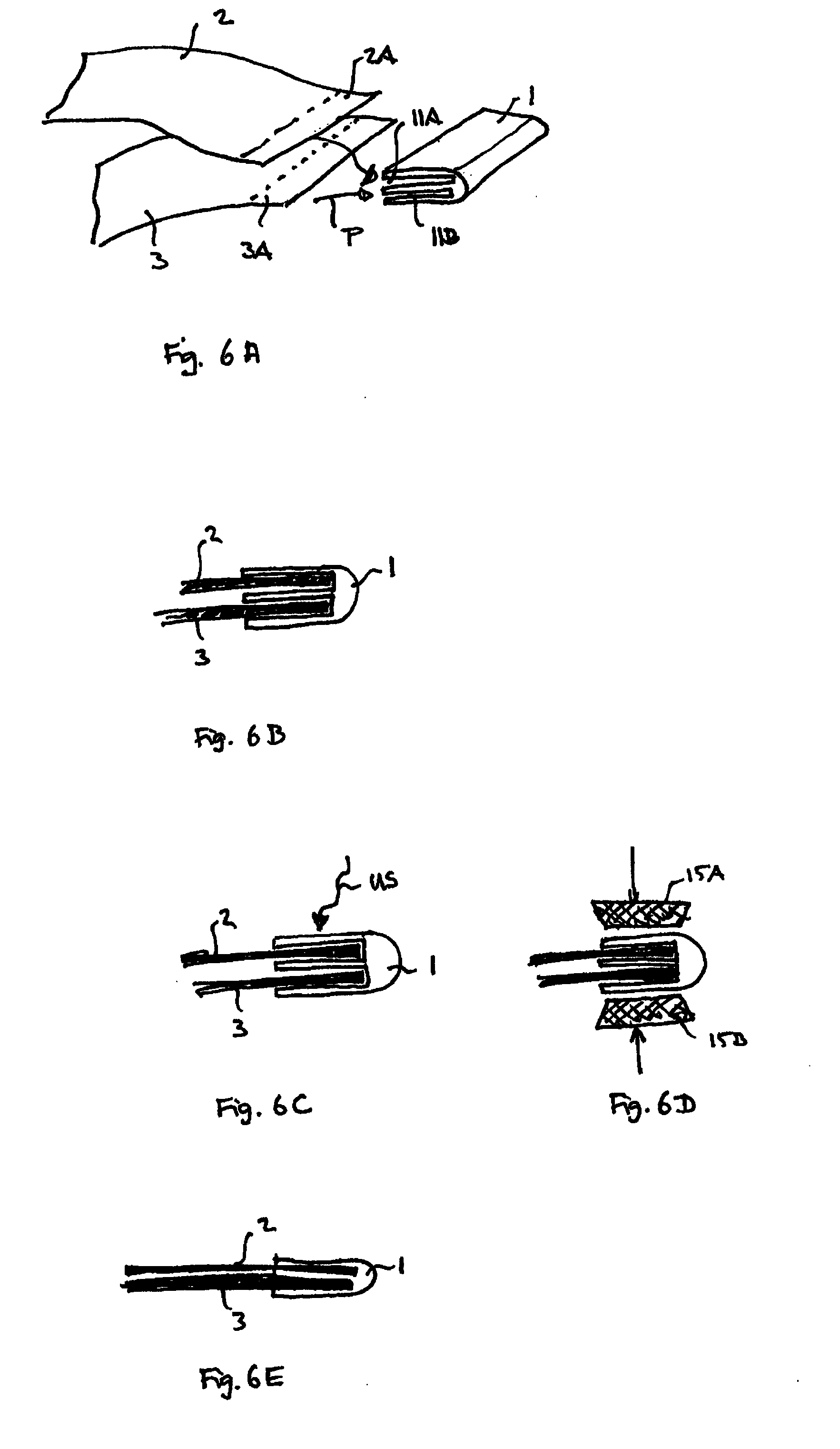
[0045]In FIG. 5, a third embodiment of a connecting element is illustrated. The connecting element 9 has in this context five legs 9A-9D wherein four intermediate spaces 11A-11D are formed into which a respective end section of the filter media to be connected can be inserted. This is indicated by the arrows P. Into the intermediate spaces 11A-11D, for example, the individual layers of the multilayer filter material sheets to be connected can be inserted. It is however also conceivable to connect in case of certain filter element geometries several of the filter material sheets with each other. As a result of the configuration of the connecting element, between the filter layers to be connected a material section is formed that is comprised of the leg material. This leads to a particularly good connection of all flat media to be connected.
[0046]In FIG. 6, several illustrations of method states for connecting flat filter media with use of a connecting element as described above are i...
Example
[0053]FIG. 8 shows a profile view of a fourth embodiment of a connecting element. The connecting element 17 has again in cross-section three legs 16A, 16B, 16C that converge at a common edge 17. Between the respective legs 16A, 16B and 16A, 16C there are wedge-shaped openings or insertion means 11A, 11B. The legs 16A, 16B, 16C are thus substantially straight and, beginning at the common edge 17, extend in a fan shape. By means of the, for example adjustable, angle between two legs each, the insertion of the material end section can be facilitated.
PUM
Property
Measurement
Unit
Electric charge
aaaaa
aaaaa
Electric charge
aaaaa
aaaaa
Electric charge
aaaaa
aaaaa
Abstract
A connecting element (1) for connecting at least two end portions (2A, 3A) of a flat filter medium (2, 3) has at least three legs (1A, 1B, 1C), one end portion (2A, 2B) each being introducible between two legs (1A, 1B, 1C). Under the influence of heat it is possible to connect the material of the legs with the material of the filter medium (2). The connecting element (1) can be used in a filter element (4) and in particular in a filtering device (5), for example an operating fluid filter for a motor vehicle. The object of a method for connecting at least two end portions (2A, 3A) of a flat filter medium (2, 3) is that the end portions (2A, 3A) are introduced between two legs (1A, 1B, 1C) each of a corresponding connecting element (1) and that through heating the material of the legs is connected with the material of the filter medium (1).
Description
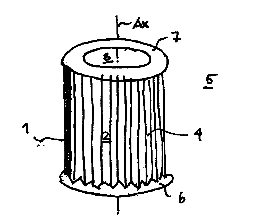
TECHNICAL FIELD[0001]The present invention concerns a connecting element for multilayer media such as, for example, nonwoven filter materials used in filter elements. Moreover, a filter element, a filter device, and a method for connecting flat media is disclosed.[0002]In order to filter, for example, in the automotive field, fluids such as fuels, operating media or passenger compartment air, folded or pleated nonwoven filter materials are often used. In this connection, it is often required to connect different edges or end sections of these flat filter materials to each other. Known filter elements, for example, are manufacture of initially zigzag-shape folded filter material sheets that are shaped to a tubular body. In order to close the tubular body, the end sections of the folds must then be connected to each other fluid-tightly.PRIOR ART[0003]In the past, in this context metal clips or clamps were used, for example, that hold together two flat sections resting on each other. I...
Claims
Application Information
Patent Timeline
Application Date:The date an application was filed.
Publication Date:The date a patent or application was officially published.
First Publication Date:The earliest publication date of a patent with the same application number.
Issue Date:Publication date of the patent grant document.
PCT Entry Date:The Entry date of PCT National Phase.
Estimated Expiry Date:The statutory expiry date of a patent right according to the Patent Law, and it is the longest term of protection that the patent right can achieve without the termination of the patent right due to other reasons(Term extension factor has been taken into account ).
Invalid Date:Actual expiry date is based on effective date or publication date of legal transaction data of invalid patent.

