Heat sink

Inactive Publication Date: 2012-03-15
NIPPON SOKEN +1
View PDF18 Cites 7 Cited by
  • Summary
  • Abstract
  • Description
  • Claims
  • Application Information

AI Technical Summary

Benefits of technology

[0015]With the above configurations of the first to the fourth heat sinks, it is possible to first temporarily assemble the heat-dissipating fins to the pillar member and then joining (e.g., brazing) the heat-dissipating fins to the pillar member in the temporarily-assembled state. As a result, it is possible to make the heat sinks without employing any additional pressing or fixing devices, thus facilitating the manufacture of the heat sinks.
[

Problems solved by technology

With the above configuration, however, it is necessary to form the grooves in the side surface of the base, thus complicating the manufacture of the heat sink.
Moreover, when the spaces between the heat-dissipating fins are small and/or the outer di

Method used


Image

  • Heat sink
  • Heat sink
  • Heat sink

Examples


Example

First Embodiment

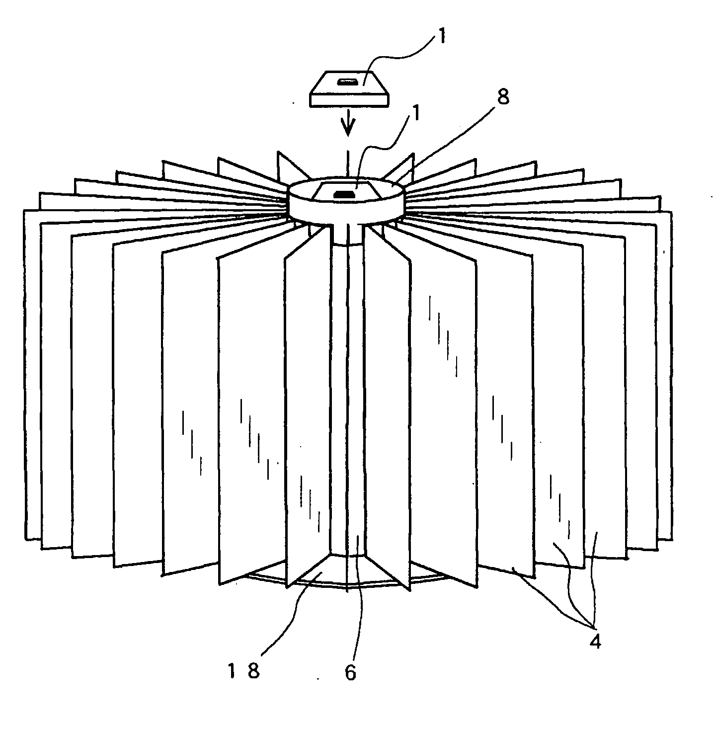
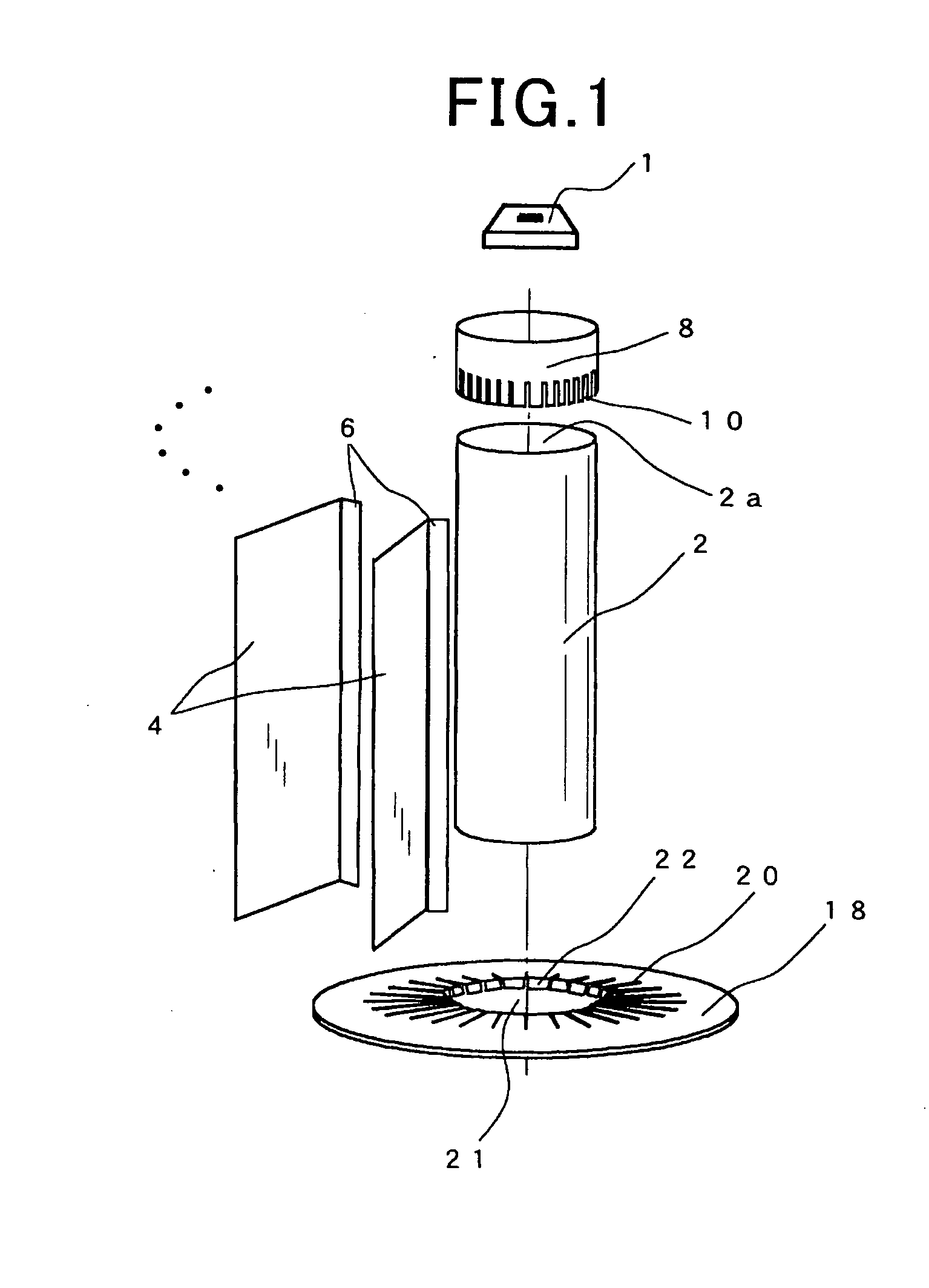
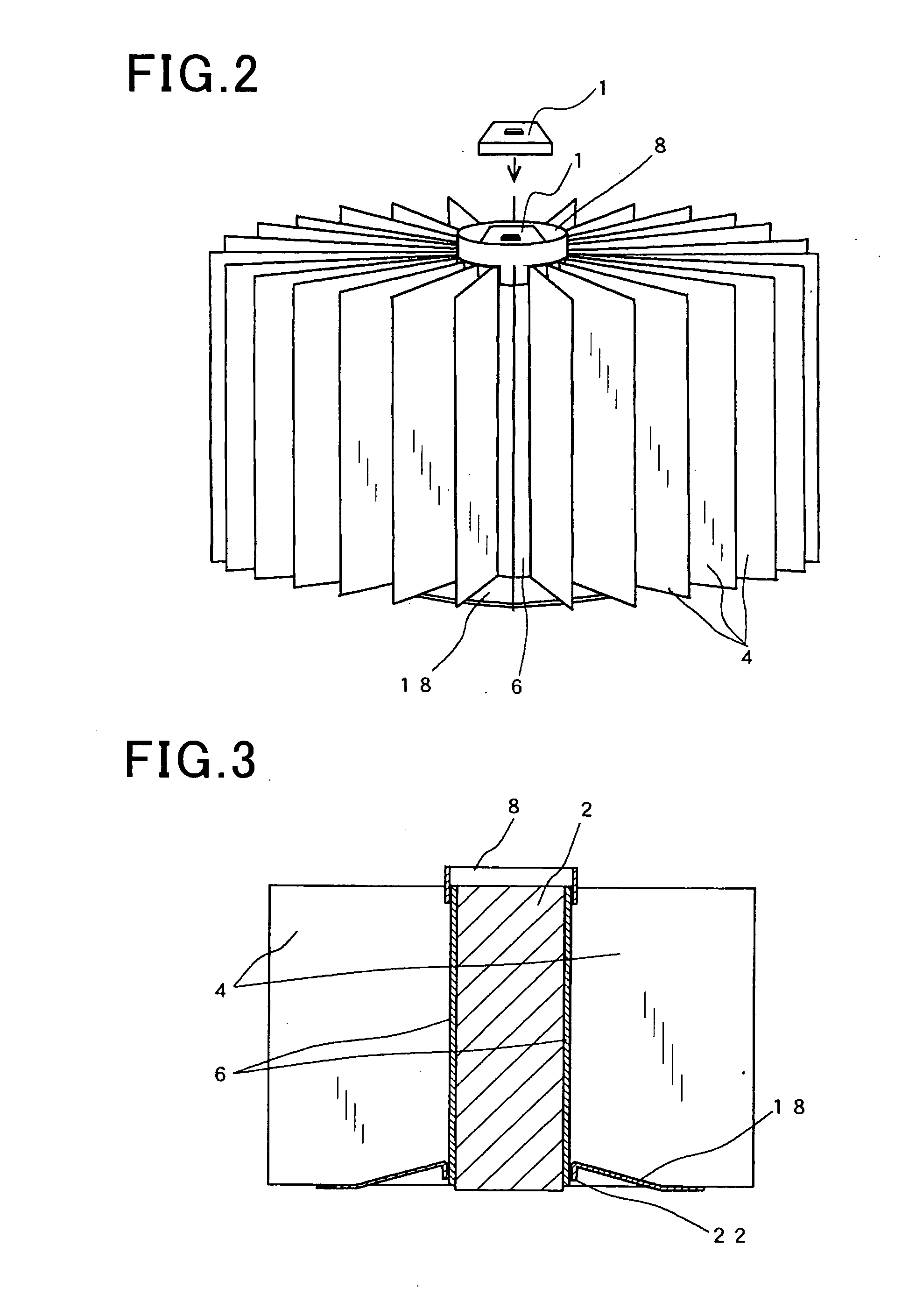
[0051]FIGS. 1-4 show the configuration of a heat sink according to a first embodiment of the invention. The heat sink is designed to dissipate heat generated by a device 1 which may be, for example, an LED (Light Emitting Diode) used in a headlamp for a vehicle.

[0052]As shown in FIGS. 1-4, the heat sink includes a pillar member 2 and a plurality of heat-dissipating fins 4.

[0053]In the present embodiment, the pillar member 2 has a cylindrical shape and is made of, for example, aluminum. The pillar member 2 has an upper end face 2a on which the device 1 is mounted.

[0054]In addition, it should be noted that the pillar member 2 may also have other shapes, for example a tubular shape.

[0055]The heat-dissipating fins 4 are provided on the radially outer periphery of the pillar member 2. The heat-dissipating fins 4 are plate-shaped and made of, for example, aluminum. In the present embodiment, the length of the heat dissipating fins 4 in the vertical direction is substantial...

Example

Second Embodiment

[0087]FIGS. 11 and 12 show the configuration of a heat sink according to a second embodiment of the invention. The head sink according to the present embodiment is similar to that according to the first embodiment; therefore, only the differences therebetween will be described hereinafter.

[0088]In the present embodiment, the heat sink includes a plurality of heat-dissipating fins 24 instead of the heat-dissipating fins 4 in the first embodiment, and a washer member 30 and a bolt 32 instead of the holding member 18 in the first embodiment.

[0089]More specifically, in the present embodiment, each of the heat-dissipating fins 24 has a first detachment prevention portion 26 and a second detachment prevention portion 28. The first detachment prevention portion 26 is identical to the detachment prevention portions 6 of the heat-dissipating fins 4 in the first embodiment. The second detachment prevention portion 28 extends radially inward from the lower end of the first det...

Example

Third Embodiment

[0094]FIGS. 15-17 show the configuration of a heat sink according to a third embodiment of the invention. The head sink according to the present embodiment is similar to that according to the first embodiment; therefore, only the differences therebetween will be described hereinafter.

[0095]In the present embodiment, the heat sink includes a plurality of heat-dissipating fins 34 instead of the heat-dissipating fins 4 in the first embodiment.

[0096]More specifically, in the present embodiment, each of the heat-dissipating fins 34 has a detachment prevention portion 36 and a slit 38. The detachment prevention portion 36 is identical to the detachment prevention portions 6 of the heat-dissipating fins 4 in the first embodiment. The slit 38 is formed so as to extend from the upper end of the heat-dissipating fin 34 downward and adjoin the detachment prevention portion 36.

[0097]In assembling the heat sink, each of the heat-dissipating fins 34 is inserted in a corresponding ...


PUM


Abstract

A heat sink includes a pillar member, to which a device that generates heat is to be mounted, and a plurality of heat-dissipating fins arranged on a side surface of the pillar member to dissipate the heat generated by the device. The heat sink further includes a ring-shaped holding member that has a plurality of grooves formed therein. The holding member is mounted to a longitudinal end of the pillar member and has each of the heat-dissipating fins inserted in a corresponding one of the grooves of the holding member, thereby holding the heat-dissipating fins to the pillar member. Each of the heat-dissipating fins has a detachment prevention portion that prevents the heat-dissipating fin from being detached from the pillar member in a direction perpendicular to the longitudinal direction of the pillar member.

Description

CROSS-REFERENCE TO RELATED APPLICATION[0001]This application is based on and claims priority from Japanese Patent Application No. 2010-206793, filed on Sep. 15, 2010, the content of which is hereby incorporated by reference in its entirety into this application.BACKGROUND OF THE INVENTION[0002]1. Technical Field of the Invention[0003]The present invention relates generally to heat sinks which have heat-dissipating fins for dissipating heat generated by devices. More particularly, the invention relates to heat sinks which dissipate heat generated by devices that have high heat-generating density and are remarkably lowered in both performance and service life at high temperature; those devices include, for example, LEDs (Light Emitting Diodes).[0004]2. Description of the Related Art[0005]Japanese Patent No. 4015146 discloses a heat sink that includes a columnar base, to which a heat-generating device is mounted, and a plurality of heat-dissipating fins provided on a radially-outer per...

Claims


Application Information

Patent Timeline
IPC IPC(8): F28F7/00
CPCF21Y2101/02H01L23/3672F21V29/77F21V29/773H01L2924/0002H01L2924/00F21Y2115/10F21W2102/00
Inventor TOMINAGA, MOTONORIKAMIZONO, TSUTOMUKATOU, MASANOBUMURASE, KATSUYUKI
Owner NIPPON SOKEN
Why Eureka
Try Eureka