Precision Safety Ring-Shaped Hook

Inactive Publication Date: 2012-05-03
AEROHOOK TECH
View PDF10 Cites 18 Cited by
  • Summary
  • Abstract
  • Description
  • Claims
  • Application Information

AI Technical Summary

Benefits of technology

[0006]The present invention provides a precision safety ring-shaped hook, which generally improves the structure o

Problems solved by technology

However, the inventor does not complacent and discovers that the free end of the locking member thereof may cause interference and impaction with the hook body during the opening and shutting of the hoo

Method used


Image

  • Precision Safety Ring-Shaped Hook
  • Precision Safety Ring-Shaped Hook
  • Precision Safety Ring-Shaped Hook

Examples


Example

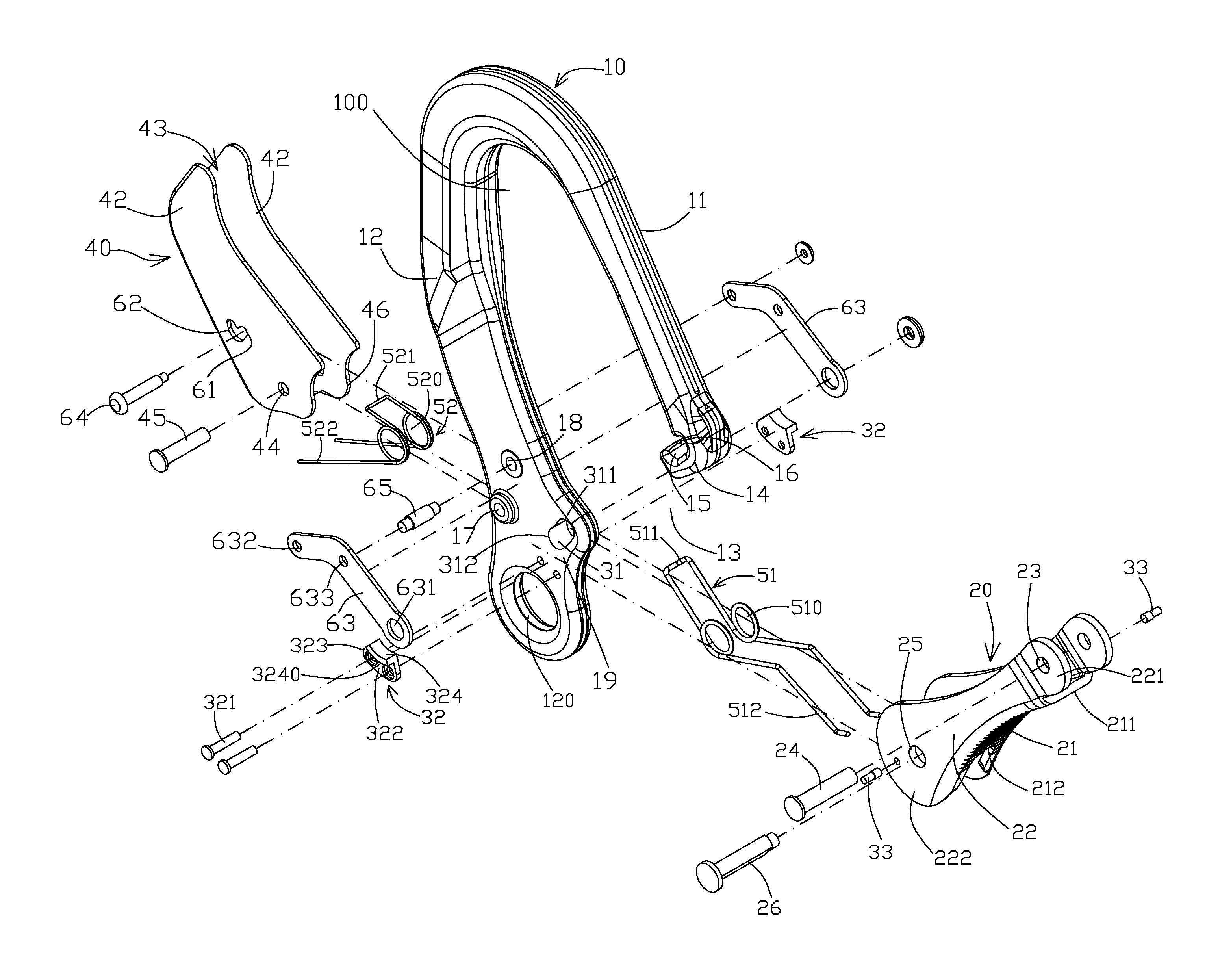
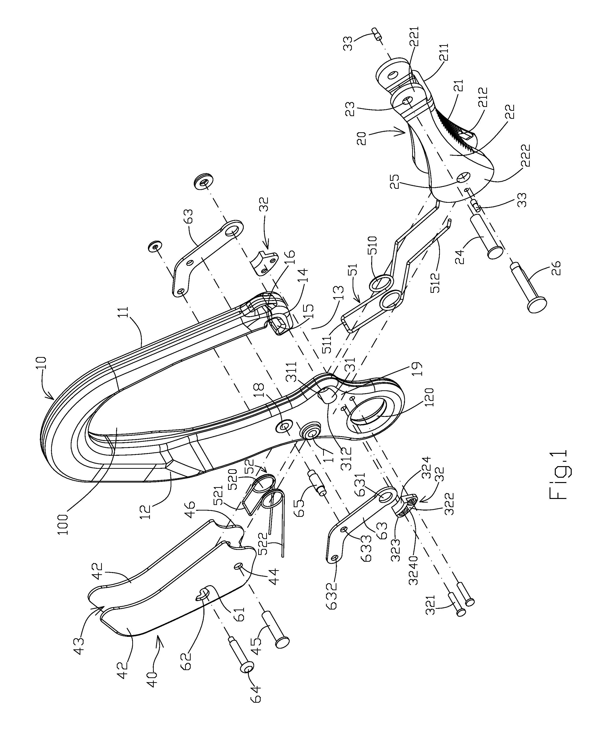
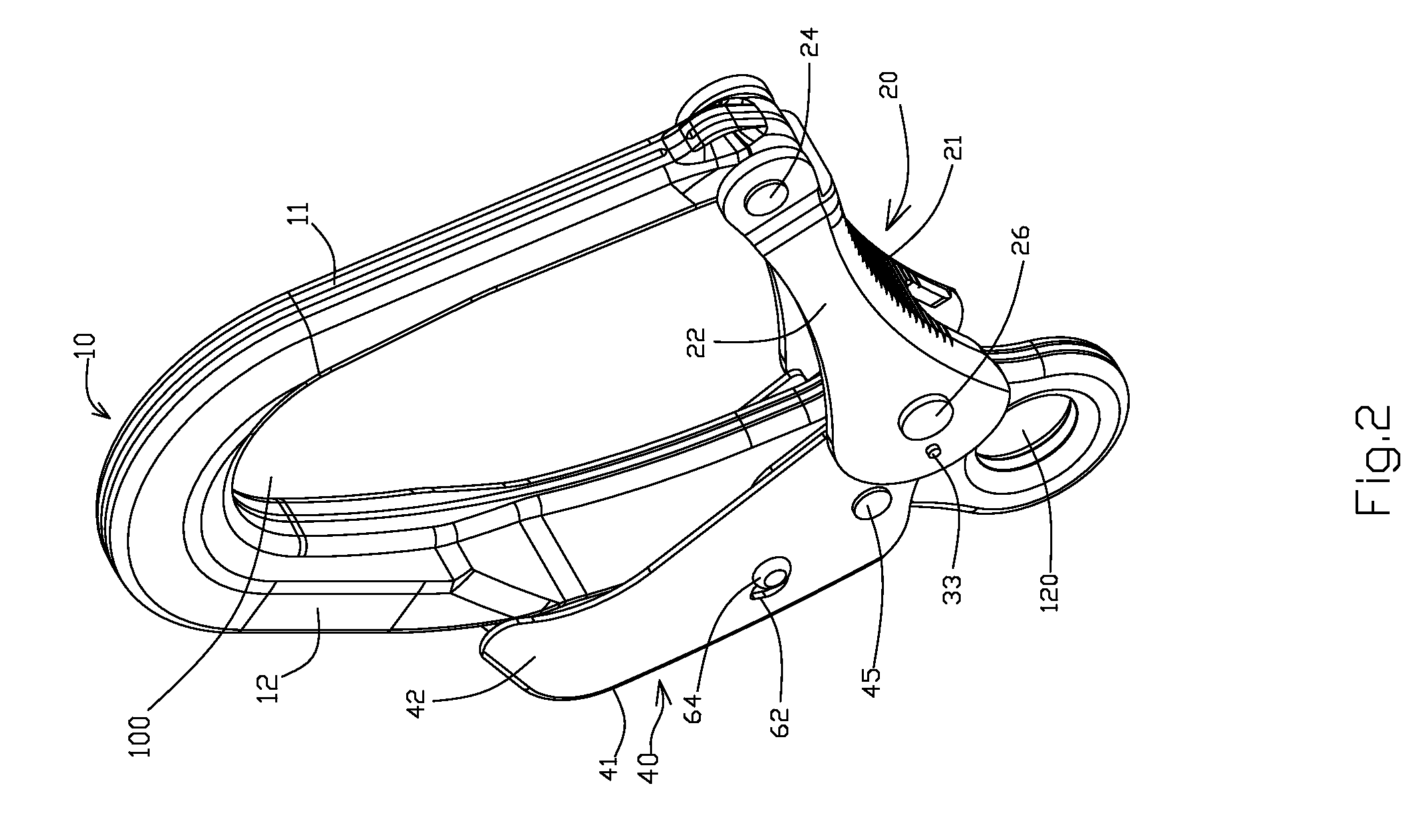
[0017]Referring to FIGS. 1-6, a precision safety ring-shaped hook according to a preferred embodiment is illustrated, which include a hook body 10 comprising a first arm 11 and a second arm 12, wherein a first end of the first arm 11 is continuously extended to connect with a first end of the second arm 12 defining a closing portion while a second end of the first arm 11 and a second end of the second arm define an opening 13 so as to define a hook cavity 100, penetrating through both front and rear sides of the hook body 10, between the first and second arms 11, 12 of the hook body 10, such that the hook cavity 100 communicates with outside through the opening 13 sidewardly. Another end of the second arm 12 forms a hooking hole 120 while another end of the first arm extends to form a first guiding member 14 which slightly narrows a width of the opening 13. An inner side surface of the first guiding member 14 forms an indented open slot 15 communicating with the hooking cavity 100, ...


PUM


Abstract

A precision safety ring-shaped hook provides a timing gauge structure which is composed of a sliding groove, a pair of rail members, and a block pin. Each of the rail members has an arc surface. When a first locking axle is moved to an open slot, a first end of a hook body is moved away from the first guiding member and, at the same time, a block pin moves to the arc surface area, so that when the first locking axle is swung in a hook cavity of the hook body, a driving pin is able to position at the arc surface and thus a locking member can be guided by the arc surface to open the opening of the hook body. Accordingly, the opening or shutting of the opening of the hook body by the locking member can thus be precisely operated at one time to provide an advance precision value for the hook and eliminate the interference and impacting drawbacks.

Description

BACKGROUND OF THE PRESENT INVENTION[0001]1. Field of Invention[0002]The present invention relates to a precision safety ring-shaped hook, and more particularly to a unique technique for accurately guiding a locking member to open and shut a hook opening.[0003]2. Description of Related Arts[0004]Please refer to a safety hook disclosed in a Taiwan Patent M357531. Although it provides an improved strengthen structure, it is restricted by the structural limitation that the resistant length defined by its pivot portion 311, second pivot axle 136 and restriction portion 313 is much shorter than the force applying length defined by its locking member 31. Therefore, when the free end of the locking member 31 undertakes an external side impact stress, it fails to prevent stress being concentrated at the restriction portion 313 and the blocking portion 213, so that it fails to bear much external side impact stress. Accordingly, the restriction portion 313 and the blocking portion 213 may get ...

Claims


Application Information

Patent Timeline
IPC IPC(8): F16B45/02
CPCF16B45/02Y10T24/45366Y10T24/45346F16B45/026F16B45/023F16B45/028
Inventor YANG, KAI CHIEH
Owner AEROHOOK TECH
Why Eureka
Try Eureka