
LED unit and optical source module having the same

Inactive Publication Date: 2009-05-21
HYUNDAI MOBIS CO LTD
View PDF4 Cites 21 Cited by
  • Summary
  • Abstract
  • Description
  • Claims
  • Application Information

AI Technical Summary

Benefits of technology

[0010]Therefore, the present invention has been made in view of the above problems, and it is an object of the present invention to provide an LED unit having an improved structure, which achieves a DRL function without a DRL provided separately from a head lamp and a fog lamp, and an optical source module having the LED unit.

Problems solved by technology

The method, in which the separate DRL unit is used with the head lamp or the fog lamp, requires the separate DRL unit, is complicated in configuration of a circuit, and causes a difficulty in mass production due to an internally built-in manipulation switch.
However, the above-described conventional lighting apparatus requires a DRL provided separately from a head lamp and a fog lamp, and thus additionally requires parts for manufacturing and installing the DRL and a manufacturing process thereof and requires a separate space for installing the DRL so as to achieve the function of the DRL in the lighting apparatus, thereby restricting the structure and design of the lighting apparatus and a vehicle having the lighting apparatus.
Further, costs and time taken to manufacture the lighting apparatus and the vehicle having the lighting apparatus are increased, and the total weight of the lighting apparatus and the vehicle having the lighting apparatus is increased.

Method used


Image

  • LED unit and optical source module having the same
  • LED unit and optical source module having the same
  • LED unit and optical source module having the same

Examples


Embodiment Construction

[0035]Now, with reference to the annexed drawings, an LED unit and an optical source module having the same in accordance with one embodiment of the present invention will be described in detail. For convenience of description, an LED unit, provided in a lighting apparatus of a vehicle, and an optical source module having the same are taken as an example. Here, the thicknesses of lines or the sizes of the elements shown in the drawings may be exaggerated for clearness and convenience of description. Also, the terms used in the following description are terms defined taking into consideration the functions obtained in accordance with the present invention. The definitions of these terms should be determined based on the whole content of this specification because they may be changed in accordance with the option of a user or operator or a usual practice.

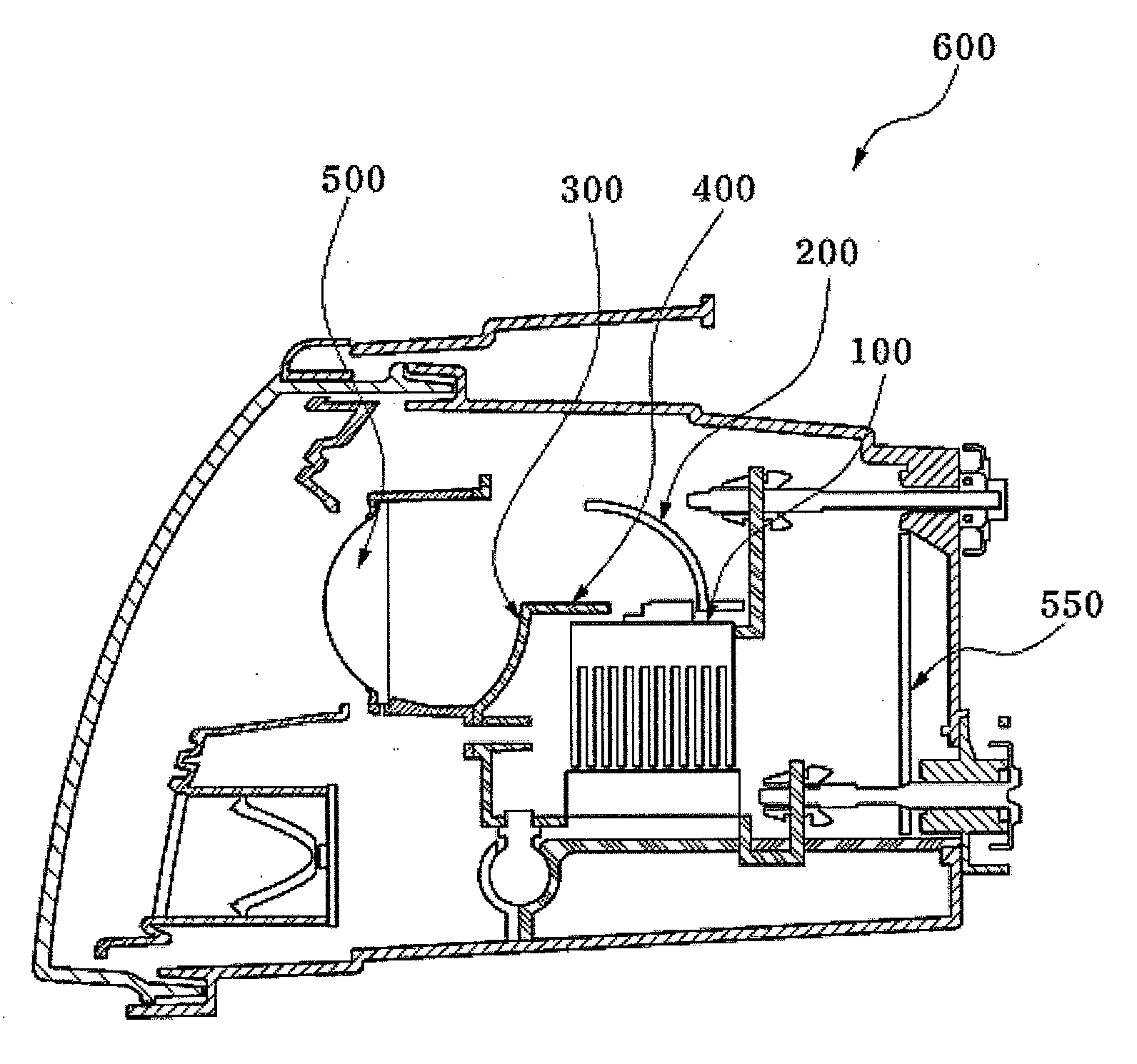
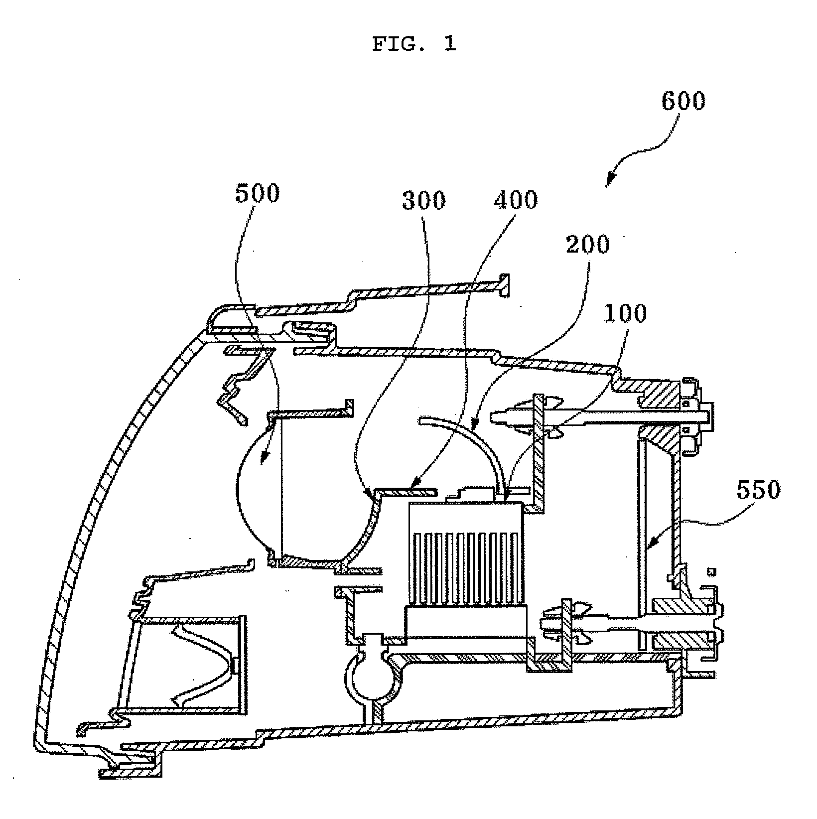
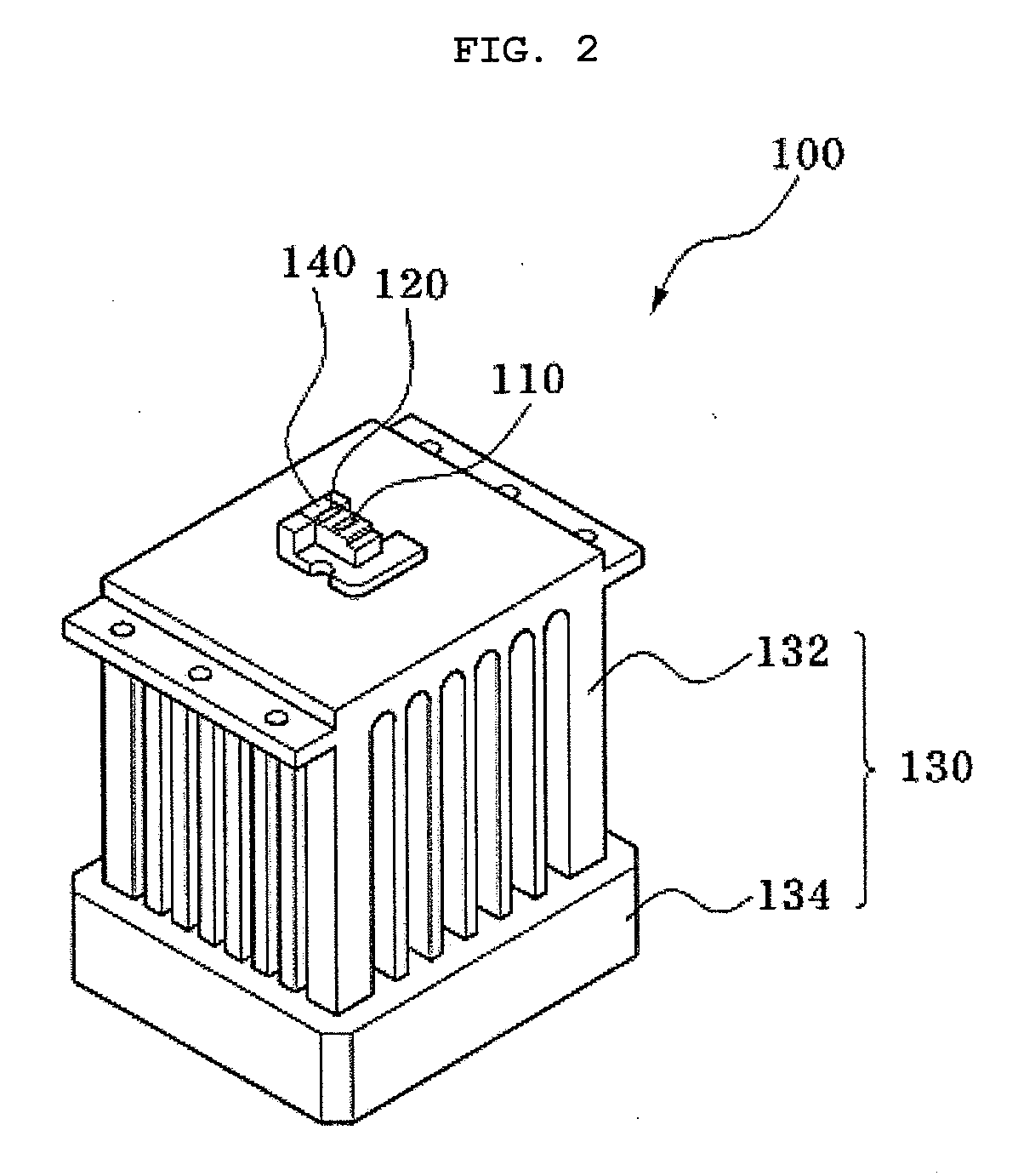
[0036]FIG. 1 is a schematic longitudinal sectional view of an optical source module in accordance with one embodiment of the present...


PUM


Abstract

Disclosed are an LED unit, provided in a lighting apparatus, and an optical source module having the same. The LED unit includes a first LED array emitting a first irradiation light; and a second LED array lighted up separately from the first LED array or together with a portion of the first LED array and thus emitting a second irradiation light.

Description

BACKGROUND OF THE INVENTION[0001]1. Field of the Invention[0002]The present invention relates to an LED unit, and more particularly to an LED unit, provided in a lighting apparatus, and an optical source module having the same.[0003]2. Description of the Related Art[0004]In general, lighting apparatuses for stably obtaining a driver's field of vision even when the intensity of surrounding illumination is low during driving are provided in a vehicle. Among these lighting apparatuses, head lamps are divided into a high beam unit and a low beam unit according to the irradiation angle and the amount of light irradiated from the lamps. The operations of the high beam unit and the low beam unit are respectively controlled by the manipulation of a multi-functional switch provided at the side of a steering wheel.[0005]Further, a fog lamp is a subsidiary lamp for obtaining the driver's field of vision in inclement weather, such as snow, rain, or fog. The fog lamp lights a place nearer than t...

Claims


Application Information

Patent Timeline
IPC IPC(8): F21V13/04
CPCB60Q1/20B60Q1/28B60Q2300/054B60Q2400/30F21V29/80F21S48/1747F21S48/328F21V29/004B60Q1/076F21S48/1159F21S41/663F21S45/43F21V29/67F21V29/74F21S41/148F21S45/40F21S41/147
Inventor AN, YOU KUN
Owner HYUNDAI MOBIS CO LTD
Learn More