Method and apparatus for high-speed calibration and rectification of a stereo camera

a technology for rectification and calibration of stereo cameras, applied in electrical equipment, pictoral communication, television systems, etc., can solve the problems of reducing mass production productivity, requiring the largest amount of time for the calibration and rectification process, and inevitably increasing the time required for the calibration and rectification of stereo cameras, so as to achieve high speed and reduce the effect of tim

Active Publication Date: 2012-05-03
VISION ST
View PDF2 Cites 17 Cited by
  • Summary
  • Abstract
  • Description
  • Claims
  • Application Information

AI Technical Summary

Benefits of technology

The technical effect of this patent is that it provides a faster way to calibrate and adjust a stereo camera system by creating a special pattern image that can be used to reduce the amount of time needed for these tasks.

Problems solved by technology

The technical problem addressed in this patent text is the time-consuming and manual process of calibration and rectification for stereo cameras, which is the main factor reducing productivity in mass production. The conventional method requires a long time to acquire pattern images and calculate calibration and rectification parameters, leading to increased production time. This patent proposes a solution to automate the calibration and rectification process, reducing the time required for the process.

Method used


Image

  • Method and apparatus for high-speed calibration and rectification of a stereo camera
  • Method and apparatus for high-speed calibration and rectification of a stereo camera
  • Method and apparatus for high-speed calibration and rectification of a stereo camera

Examples


Embodiment Construction

[0043]Reference will now be made in greater detail to a preferred embodiment of the invention, an example of which is illustrated in the accompanying drawings. Wherever possible, the same reference numerals will be used throughout the drawings and the description to refer to the same or like parts.

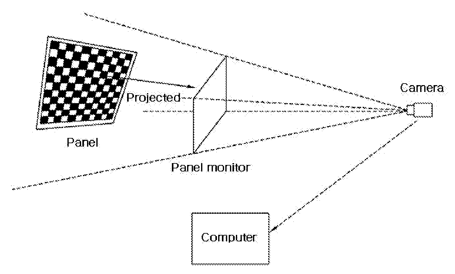
[0044]In the conventional calibration and rectification method for a stereo camera, a person should carry a grid-pattern panel and take a posture to acquire a 3D image. In the embodiment of the present invention, however, a 3D graphical technique is used to acquire a 3D image within a short time. Therefore, the calibration and rectification may be performed at high speed.

[0045]FIG. 7 is a diagram explaining a concept for implementing a high speed calibration and rectification method for a stereo camera according to an embodiment of the present invention.

[0046]The camera is arranged at a predetermined position, and it is assumed that an arbitrary plane perpendicular to the optical axis of t...


PUM


Abstract

A calibration and rectification method includes arranging a monitor vertically relative to the optical axis of the stereo camera; displaying 3D patterns, similar to patterns obtained by projecting pattern images of various postures produced by a panel virtually located in front of the stereo camera, onto the monitor through a 3D graphical technique; and the stereo camera acquiring the 3D patterns displayed on the monitor to perform calibration and rectification, thereby correcting images of the stereo camera.

Description


Claims


Application Information

Patent Timeline
Owner VISION ST
Why Eureka
Try Eureka