
Single Virtual Domain Fibre Channel over Ethernet Fabric

a fibre channel and single virtual domain technology, applied in the field of single virtual domain fibre channel over ethernet fabric, can solve the problems of domain_id exhaustion and difficulties in both the existing fibre channel fabric and the fcoe fabri

Active Publication Date: 2012-05-03
AVAGO TECH INT SALES PTE LTD
View PDF15 Cites 61 Cited by
  • Summary
  • Abstract
  • Description
  • Claims
  • Application Information

AI Technical Summary

Benefits of technology

The present invention provides a single virtual domain for the FCoE fabric, even though there may be multiple FCFs and FDFs. The virtual domain has a different Domain_ID than any of the FCFs used to connect the FCoE fabric to the FC SAN. The node port IDs are not based on the particular FDFs or FCFs which they connect through. There may be multiple FCFs, with one designated as the master and the others as slaves for failover and multipathing. Virtual links are instantiated between the master and slave FCFs, as well as between top level and second level FDFs. The ENodes are connected to FDFs or to FCFs, and the FDFs effectively proxy the master for most FIP operations. The master FCF performs routing analysis and provides it to the other FCFs and FDFs. The routing is performed using either the FSPF protocol conventionally used in Fibre Channel or a combination of FSPF and adjacency information based on FDF connections. The technical effects of the invention include simplified network design, improved failover and multipathing, and efficient routing between ENodes.

Problems solved by technology

The concern is that the sheer number of these devices when installed both top of rack (TOR) and end of row (EOR) will result in Domain_ID exhaustion.
This Domain_ID exhaustion could create difficulties in both the existing Fibre Channel fabric and in the FCoE fabric.
While this did address the Domain_ID exhaustion issue, it resulted in other issues relating to failover, multipathing and the like.

Method used


Image

  • Single Virtual Domain Fibre Channel over Ethernet Fabric
  • Single Virtual Domain Fibre Channel over Ethernet Fabric
  • Single Virtual Domain Fibre Channel over Ethernet Fabric

Examples


Embodiment Construction

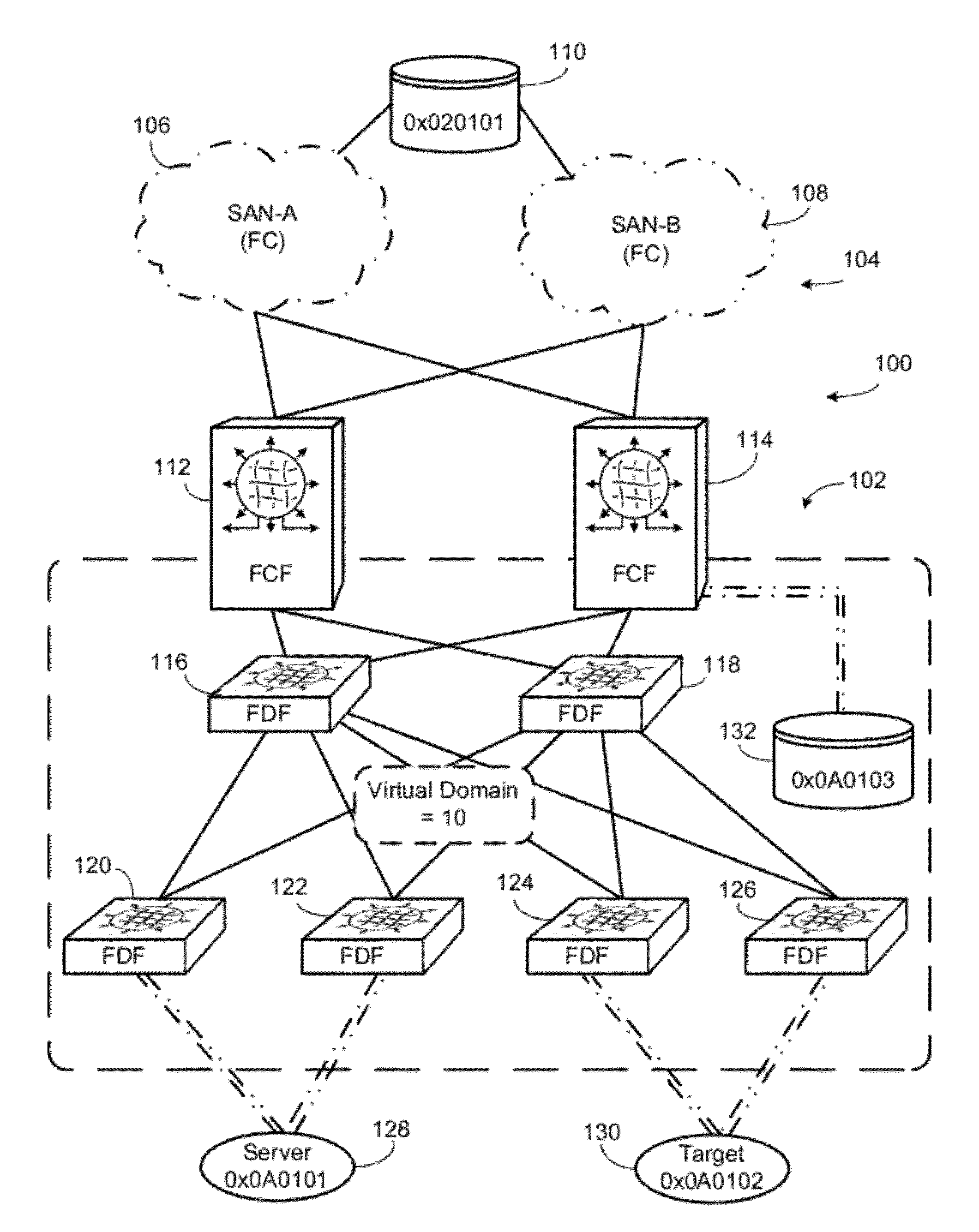
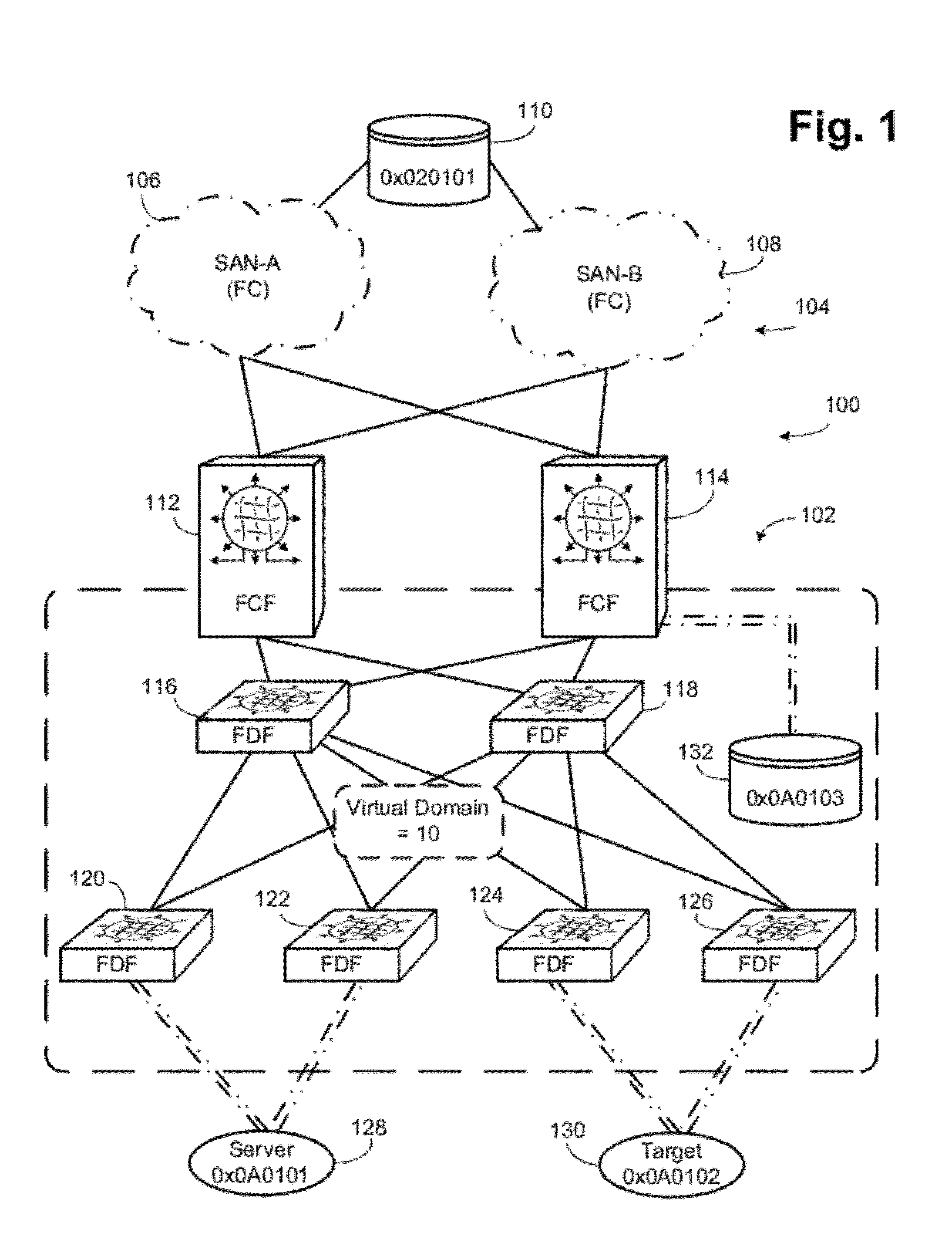
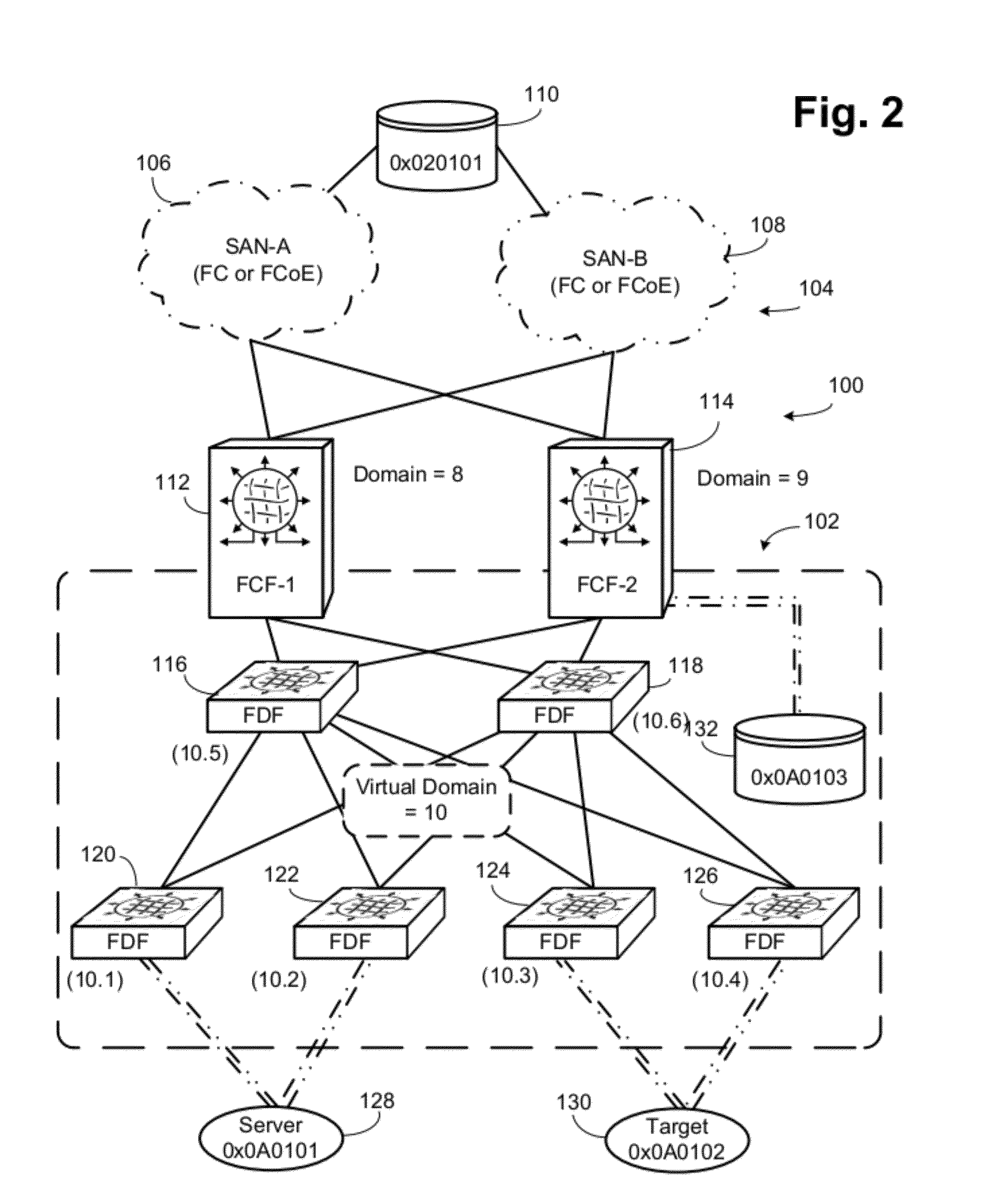
[0033]Referring to FIG. 1, a network 100 according to the present invention is illustrated. The network 100 includes a Fibre Channel over Ethernet (FCoE) network portion 102 and a Fibre Channel (FC) network portion 104. The Fibre Channel network portion 104 includes a fabric SAN-A 106 and a fabric SAN-B 108. An exemplary storage unit 110 is connected to both fabrics 106 and 108 in normal Fibre Channel redundant operation. Connected to the fabrics 106 and 108 are FCoE forwarders (FCFs) 112 and 114. These two FCFs form the interface between the FCoE network portion 102 and the Fibre Channel network portion 104. Connected to each of the FCFs 112, 114 are two FCoE data forwarders (FDFs) 116 and 118. Connected to each of the FDFs 116 and 118 are FDFs 120, 122, 124 and 126. An exemplary server 128 is connected to FDFs 120 and 122. An exemplary target 130 is connected to FDFs 124 and 126. An exemplary storage unit 132 is connected to the FCF 114.

[0034]The FCoE network portion 102 is treate...


PUM


Abstract

The entire FCoE fabric is a single virtual domain, even though there may be multiple FCFs and FDFs. The virtual domain is a different Domain_ID than any of the FCFs. In certain embodiments there are multiple FCFs, of which one is selected as the master or designated FCF. The master FCF performs normal fabric configuration in conjunction with the Fibre Channel fabric. The master FCF assigns the virtual domain FC node IDs and controls development of subdomain IDs. Virtual links are instantiated between the master FCF and other FCFs, between top level FDFs and the FCFs and between the FDFs at each of various levels. FDFs connected to ENodes proxy the master FCF for most FIP operations. FIP FLOGI and FDISC operations are handled by the master FDF, but the FDFs convert the FIP FLOGI requests to VD_FLOGI requests, which include information about the FDF handling the transaction.

Description

CROSS REFERENCE TO RELATED APPLICATIONS[0001]This application claims the benefit under 35 U.S.C. §119(e) of U.S. Provisional Patent Applications Ser. No. 61 / 333,610, entitled “Single Domain FCoE Fabrics,” filed May 11, 2010, which is hereby incorporated by reference.BACKGROUND OF THE INVENTION[0002]1. Field of the Invention[0003]The invention relates to networking fabrics, and more particularly to Fibre Channel over Ethernet fabrics.[0004]2. Description of the Related Art[0005]Fibre Channel over Ethernet (FCoE) is a developing standard to enable Fibre Channel operations over an Ethernet network. Many uses of an FCoE fabric will be to connect to existing Fibre Channel fabrics. The interface between the Fibre Channel over Ethernet fabric and the Fibre Channel fabric is a device called the FCoE Forwarder (FCF).[0006]One restriction of Fibre Channel is a 239 Domain_ID limitation. In conventional Fibre Channel operation each switch consumes a Domain_ID. Many of the perceived implementati...

Claims


Application Information

Patent Timeline
Patent Type & Authority Applications(United States)
IPC IPC(8): H04J14/00H04B10/20
CPCH04L29/12207H04L29/12886H04L61/20H04L61/6045H04L61/50H04L2101/645
Inventor WILLEKE, JESSE BREWSTERCHUNG, DANIEL JI YONG PARKPETERSON, DAVID ALANWENIG, GLENN CHARLESVOBBILISETTY, SURESHKOGANTI, PHANIDHAR
Owner AVAGO TECH INT SALES PTE LTD
Learn More