Method for creating a linear programming model of an industrial process facility

a technology of industrial process and linear programming, applied in the direction of adaptive control, instruments, solidification, etc., can solve the problems of large computer time and resources required to run a model, the difficulty of effectively controlling and optimizing the operation of an industrial process facility, and the computational intensity of first principles reference models

Active Publication Date: 2007-08-14
EXXONMOBIL CHEM PAT INC
View PDF11 Cites 38 Cited by
  • Summary
  • Abstract
  • Description
  • Claims
  • Application Information

AI Technical Summary

Benefits of technology

[0057]An important advantage of the present invention is that because the entire steam cracker is solved simultaneously, the need to create individual derived models of the various process units is eliminated. This avoids having to deal with recycle streams to previous process units (their impact is intrinsically and correctly contained in the partial derivatives contained in the LP matrix), and thus greatly simplifies the development of the LP. Also, other interactions among process units (e.g., interactions resulting from sharing a common refrigeration system) are also correctly accounted for in the LP, since the first principles reference model correctly depicted these interactions as it was solved and the partial derivatives for the LP were created. The fact that the effects of recycle streams and other interactions between process units are accurately accounted for in the LP results (even though these elements are not depicted in the LP) is a major advantage that was unknown and unexpected prior to Applicants' discovery thereof.
[0058]One of the most important advantages of the present invention is that it overcomes the maintenance problem, described above, that occurs when the steam cracker changes in such a way as to invalidate or make inaccurate the derived model of the steam cracker. As noted above, this can occur when, for example, the steam cracker performance changes over time (e.g., due to fouling), or operating configurations are altered (e.g., by invoking a multiple processing option), or the steam cracker's capacity utilization is significantly altered, or the steam cracker performance moves sufficiently far from the original derivation point so as to make the derived model inaccurate because of the non-linear effects in the steam cracker and, therefore, in the reference model. With the present invention, steam cracker changes (fouling, configuration, or new operating regime) are simply reflected in the first principles reference model, and the set of partial derivatives that depict the steam cracker in the LP are re-derived and updated in the LP. This can be accomplished in a relatively short period of time.
[0059]Another unexpected advantage of the present invention is that the size of the LP model can be substantially smaller than was possible with prior LP models because only the key output variables need to be represented in the final LP model. Other output variables can be included if desired, but only the key output variables need to be included in the final LP model.
[0060]FIG. 2 is a flow chart showing the principal steps of another embodiment of the present invention. This embodiment is directed to a method for creating a linear programming (LP) model of an industrial process facility that includes at least two separate sections (e.g., two steam crackers), which sections can be operated either jointly or separately. As an example, assume that the facility includes two separate sections, A and B. If sections A and B are always operated together (i.e., section A never runs without section B, and section B never runs without section A), then it is preferable to model the facility using the method described above in connection with FIG. 1 (i.e., where a single matrix is created to depict both sections A and B in the final LP model). By contrast, if either section A or section B can be independently shut down while the other section continues to operate, then it is usually preferable to create a separate matrix for each section in the final LP model. This approach facilitates simulation and optimization of only one section of the facility when the other section is shut down.
[0061]According to this embodiment, a non-linear, first principles reference model of the facility is created at step 210. If there are significant interactions between the separate sections of the facility (at least some of the time), then it is preferable to include the entire facility in a single reference model. By doing so, the interactions between the sections are modeled on a consistent basis.
[0062]Next, at step 212, a first one of the sections is selected and, at step 214, independent input variables and key output variables for the selected section are specified. As with the previous embodiment, the independent input variables would likely include feedstock flow rates and feedstock compositions (or, alternatively, flow rate for each feedstock component), flow rates for each component in all external feed streams, and critical operating parameters for the selected section, and the key output variables would likely include flow rate of each product, quality of selected products, amount of energy consumed, and values for potential system constraints.

Problems solved by technology

Difficulties arise in effectively controlling and optimizing the operation of an industrial process facility due to factors such as the wide variety of separate process units and equipment that may be contained in the facility, the large number of process variables, the large number of potential feedstocks and feedstock compositions, operating variables (e.g., flow rates, temperatures, pressures, etc.), product specifications, market constraints and prices (e.g., for feeds, products, and utilities), mechanical constraints, transportation and storage constraints, and weather conditions.
Unfortunately, first principles reference models tend to be computationally intensive and, accordingly, substantial computer time and resources can be required to run a model based thereon.
However, these tools do not have the capability to model process unit operations based on first principles, nor do they contain a thermodynamic library to describe how different molecules, components, or pseudo-components would perform in such process unit operations.
As such, these derived tools cannot directly provide heat and material balance information for use in design, equipment rating, equipment performance, simulation, and optimization of the facility.
Thus, a change in the products from a particular upstream process unit may cause a change in a recycle stream from a downstream process unit, which in turn may cause another change in the same or a different upstream process unit.
Often, the engineering tools used differ depending on the process unit being modeled, and the use of different engineering tools to create the process unit depictions can result in consistency problems within the final derived model.
Sometimes, only a simple mass balance depiction may be used, but such a simple depiction may miss important energy effects, and may not be able to represent constraints with sufficient accuracy.
There are several problems inherent in the procedure described above.
Moreover, complex steam crackers typically have a large number of recycle streams that must be accurately modeled.
When the individual derived models for each process unit and recycle streams are joined together to form the overall derived model for the facility, inconsistencies between individual derived models (e.g., inconsistencies in the underlying engineering tools or in the heat and material balance basis) can result in a more difficult validation process and, in some situations, in non-convergence or unacceptable inaccuracies in the overall model.
Obviously, the above approach to model development is very difficult.
For example, process units become fouled over time (or get cleaned).
Further, the steam cracker recovery section performance (particularly in compressor areas) is actually not linear at all.
While this performance can be adequately approximated by a linear relationship over a portion of the operating window, major moves from the original derivation point often result in significant non-linear effects that cause the original depiction and derivatives based thereon to become too inaccurate to adequately represent the steam cracker.
However, to date, none of the proposed solutions has been entirely satisfactory.
Unfortunately, the simultaneous use of multiple solvers, some of which are non-linear, can result in significant computing time and resource disadvantages.
However, given the enormous size and complexity of a first principles reference model for an entire industrial process facility, as well as its non-linear nature, solution of the model can require huge amounts of computing resources and can take substantial periods of time, especially in optimization mode.

Method used


Image

  • Method for creating a linear programming model of an industrial process facility
  • Method for creating a linear programming model of an industrial process facility
  • Method for creating a linear programming model of an industrial process facility

Examples


example

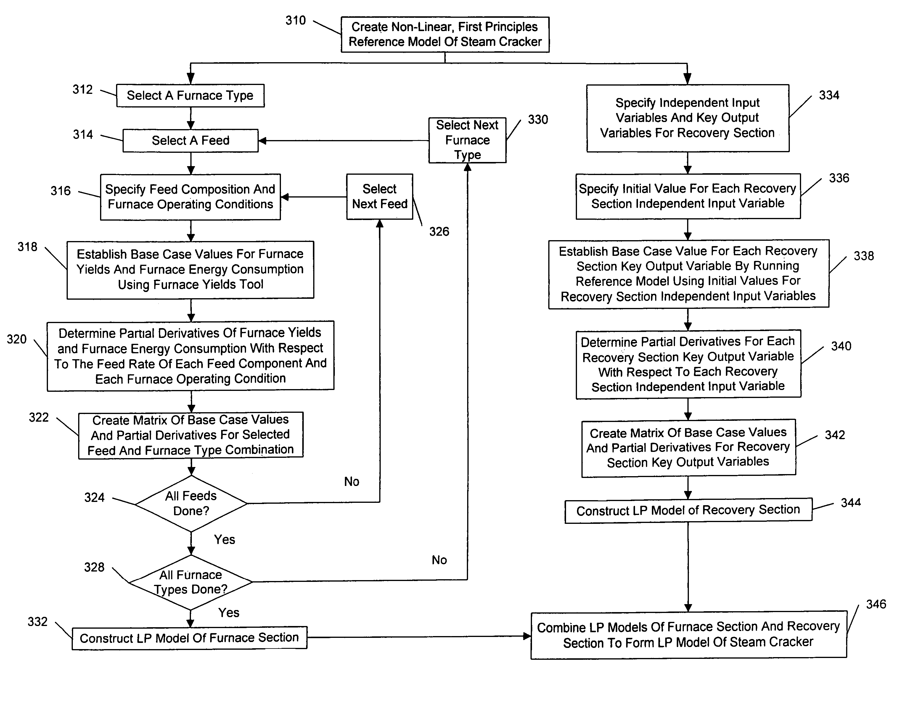
[0093]Following is an example of the use of the present invention to create a LP model of a steam cracker. For this example, the non-linear, first principles reference model of the steam cracker was constructed using the ROMeo® reference tool described above. Although typical steam cracker LP models may contain as many as 250 or more input variables and 1000 or more output variables, the example has been limited to 12 input variables and 15 output variables. It will be understood that this is for purposes of illustration only, and should not be construed or interpreted as a limitation on the scope of the invention.

[0094]FIGS. 4A and 4B show an LP matrix constructed according to the present invention for the example steam cracker. Turning first to FIG. 4A, the left hand column (column 410) lists the output variables. Column 410 is also reproduced as the left hand column on FIG. 4B for purposes of clarity. Note that column 410 also includes, in the bottom 12 rows, the 12 input variabl...


PUM


Abstract

A method for creating a linear programming (LP) model of an industrial process facility is disclosed. The model may be used for interactively simulating and / or optimizing the operation of the facility to facilitate feedstock selection and / or other economic analyses. According to the inventive method, a first principles reference tool is used to create a non-linear reference model of the entire facility. Then, independent input variables and key output variables are specified, and initial values for the independent input variables are specified. Base case values for each key output variable are determined by running the non-linear reference model using the specified initial values for the independent input variables. Next, partial derivatives for each key output variable with respect to each independent input variable are determined. A matrix is constructed containing the base case values and partial derivatives. The matrix serves as the depiction of the industrial process facility in the final LP, which may also include prices, availabilities, and other external constraints.

Description

CROSS REFERENCE TO RELATED APPLICATION[0001]This application claims the benefit of Provisional Application No. 60 / 652,961 filed Feb. 15, 2005, the disclosure of which is incorporated by reference.FIELD OF THE INVENTION[0002]This invention relates to a method for creating a linear programming (LP) model of an industrial process facility from a non-linear reference model of the facility. The resulting LP model may be used to simulate and / or optimize the operation of the facility.BACKGROUND OF THE INVENTION[0003]As used herein, the term “industrial process facility” shall mean any facility that is adapted to refine, purify, convert, consume, or otherwise process any material to produce desired products, and includes, but is not limited to, petroleum refineries, catalytic and steam crackers, petrochemical plants, other chemical plants (i.e., chemical plants that are not based on petrochemicals), facilities for converting natural gas and / or methanol into other hydrocarbons, natural gas l...

Claims


Application Information

Patent Timeline
Patent Type & Authority Patents(United States)
IPC IPC(8): G05B13/02
CPCF25J3/0219F25J3/0233F25J3/0238F25J3/0242F25J3/0247F25J3/0295G05B13/041G05B17/02F25J2210/12F25J2215/62F25J2215/64F25J2215/66F25J2270/12F25J2270/60F25J2280/02F25J2280/50
Inventor CARPENCY, JAY F.WATRET, DEREK W.
Owner EXXONMOBIL CHEM PAT INC
Why Eureka
Try Eureka