Device and method for heating up a cup

Inactive Publication Date: 2012-05-10
KONINKLIJKE PHILIPS ELECTRONICS NV
View PDF6 Cites 3 Cited by
  • Summary
  • Abstract
  • Description
  • Claims
  • Application Information

AI Technical Summary

Benefits of technology

[0006]In order to accomplish this object, the steam injection unit comprises the water sucking end portion of a water suction conduit for sucking water out of the cup. The water may be sucked out of the cup after the cup has been heated up, but preferably, the water is sucked out of the cup simultaneously with the steam injection. When a cup is heated by injection of steam into the cup, the steam will condense in the cold cup so that water accumulates in the cup. Such accumulated water will dilute the hot drink when it is brought into the cup. By sucking the accumulated water out of the cup before the cup is filled with the drink, dilution of the drink is avoided.
[0008]In a preferred embodiment, the steam conduit comprises a narrow portion so that a Venturi effect is created, causing the pressure in said narrow portion to be below the environmental air pressure, and the water suction conduit is connected with the steam conduit at the location of said narrow portion, so that water and / or air is sucked in by said Venturi effect. As a result, the water is sucked out of the cup in an effective and efficient manner, without the presence of moving parts such as a pump or a valve, and without the need for additional power supply.

Problems solved by technology

Such accumulated water will dilute the hot drink when it is brought into the cup.

Method used


Image

  • Device and method for heating up a cup
  • Device and method for heating up a cup

Examples


Embodiment Construction

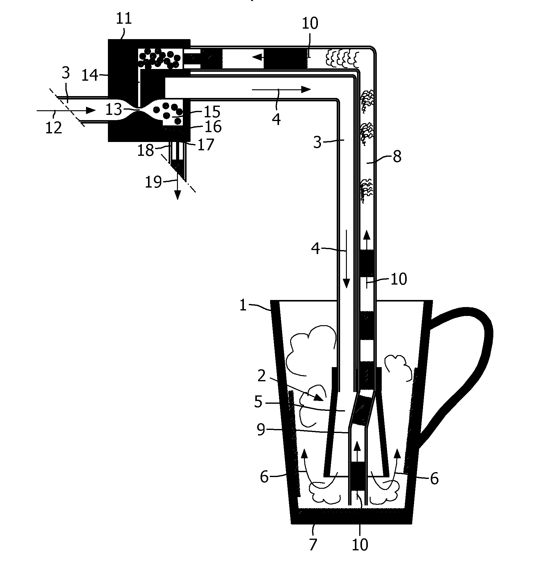
[0020]FIG. 1 shows a cup 1 and a steam injection unit 2, which steam injection unit 2 reaches into the cup 1. Steam flows to the steam injection unit 2 through a steam conduit 3 as is indicated by two arrows 4. The end of steam conduit 3 is connected to a spout member 5 having a divergent shape in downward direction. The spout member 5 can be made of flexible material such as rubber or plastic. The steam leaves the spout member 5 at its lower side, as is indicated by two arrows 6, and the cup 1 will then be heated up by condensation of the steam, whereby water 7 will accumulate in the lower part of the cup 1.

[0021]The spout member 5 is also connected with a water suction conduit 8, the end portion of the water suction conduit 8 being shaped like a hose 9 extending through the spout member 5. The hose 9 may also be made of flexible material such as plastic or rubber. The hose 9 extends beyond the lower side of the spout member 5, so that the end of the hose 9 can be located close to ...


PUM


Abstract

A device for heating up a cup, comprising a steam conduit (3) for guiding steam into the cup (1), and comprising a water suction conduit (8) for sucking water out of the cup (1). Preferably, the water suction conduit (8) is connected with the steam conduit (3) in such a manner that the flow of steam through the steam conduit (3) sucks water and / or air out of the water suction conduit (8).

Description

FIELD OF THE INVENTION[0001]The invention is related to a device for heating up a cup, comprising a steam injection unit that can reach into the cup to be heated, wherein the steam injection unit comprises the steam injecting end portion of a steam conduit. The expression ‘cup’ includes any kind of drinking container, such as a drinking glass, a goblet, a mug, etc.[0002]A device comprising a steam injection unit that can reach into a cup, wherein the steam injection unit comprises the steam injecting end portion of a steam conduit is described in US-A-2007 / 175336. Thereby, the purpose of the steam injection is not the heating of to cup, but the described device is a milk whipper of a coffee maker, whereby steam is injected into milk being present in the cup.BACKGROUND OF THE INVENTION[0003]When filling a cold cup with a warm drink, such as hot coffee, hot tea or hot chocolate, the cup will be heated up by the hot drink and, at the same time, the drink will be cooled down. In order t...

Claims


Application Information

Patent Timeline
IPC IPC(8): A23L2/00
CPCA47J31/4489A47J31/4417A47J31/44
Inventor NOORDHUIS, JOEKEVAN WIFFEREN, REINDERT JANNESCOOMBS, JAMES HOWARD
Owner KONINKLIJKE PHILIPS ELECTRONICS NV
Why Eureka
Try Eureka