Dynamic shared risk node group (SRNG) membership discovery

a dynamic and risk node technology, applied in the field of computer networks, can solve the problems of inability of each link whose data packets are transported using that shared resource, inability to use static srng configuration, excessive time-consuming manual srng configuration, etc., and achieves fast and efficient identification, the effect of updating faster and more efficiently

Inactive Publication Date: 2012-05-10
CISCO TECH INC
View PDF6 Cites 15 Cited by
  • Summary
  • Abstract
  • Description
  • Claims
  • Application Information

AI Technical Summary

Benefits of technology

[0018]Advantageously, the inventive technique enables faster and more efficient identification of SRNG memberships than static configuration implementations. The technique also enables SRNG memberships to be updated faster and more efficiently in response to network topology changes.

Problems solved by technology

That is, failure of the shared resource would result in the failures of each of the links whose data packets are transported using that shared resource.
In this case, a network failure at the common edge device would prevent each device in the SRNG from communicating with the failed edge device in the second domain.
Although manual configuration of SRNG memberships also can be performed, such static SRNG configuration is impractical.
For instance, manual SRNG configuration is excessively time consuming, since it requires a network administrator to examine each edge device in a routing domain to determine the device's directly-attached peers.
Because the administrator may have to keep track of a large number of edge devices and complex network topologies, manual SRNG configuration can result in erroneous or accidental SRNG assignments.
The above-noted problems are often compounded in response to changes in the network topology which necessitate updated SRNG assignments.

Method used


Image

  • Dynamic shared risk node group (SRNG) membership discovery
  • Dynamic shared risk node group (SRNG) membership discovery
  • Dynamic shared risk node group (SRNG) membership discovery

Examples


Embodiment Construction

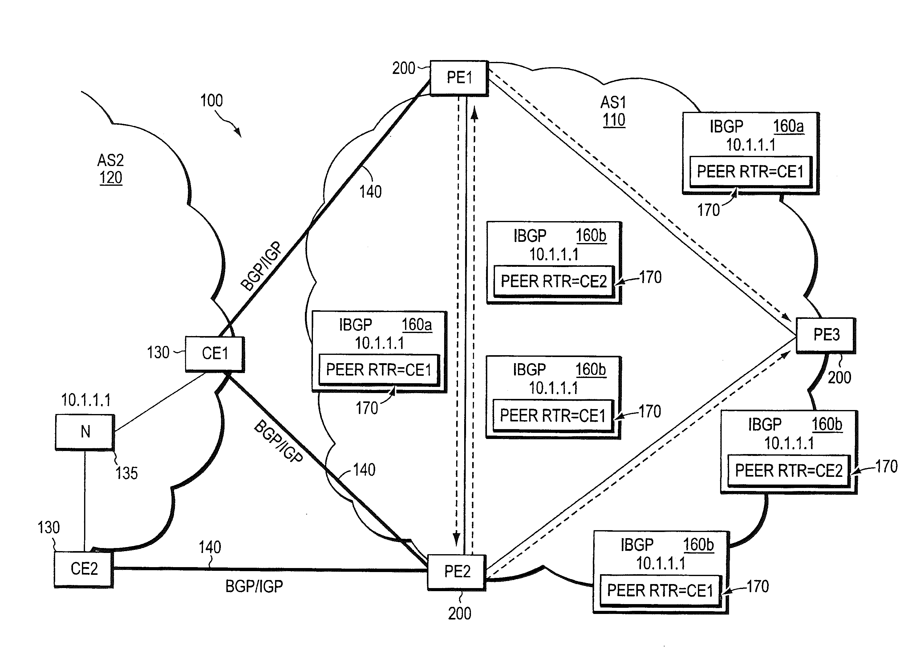
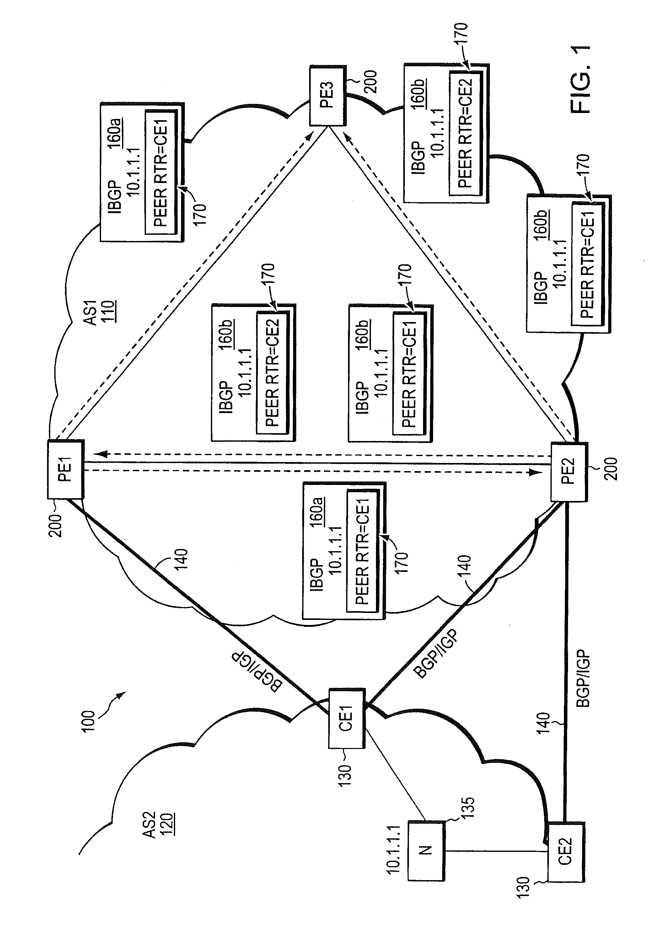
[0025]FIG. 1 illustrates an exemplary computer network 100 including a service provider network 110 (AS1) coupled to a neighboring customer site 120 (AS2). The provider network is preferably managed as BGP or Multi-Protocol Label Switching (MPLS) virtual private network (VPN) network, as generally described in the IETF publication RFC 2547, entitled BGP / MPLS VPNs, by E. Rosen et al., published March 1999, which publication is hereby incorporated by reference as though fully set forth herein. Data packets are forwarded between nodes in the provider network 110 using, e.g., the IP and / or MPLS protocols, and routing information is exchanged among the intermediate network nodes using an interior gateway routing protocol (IGP), such as OSPF or IS-IS.

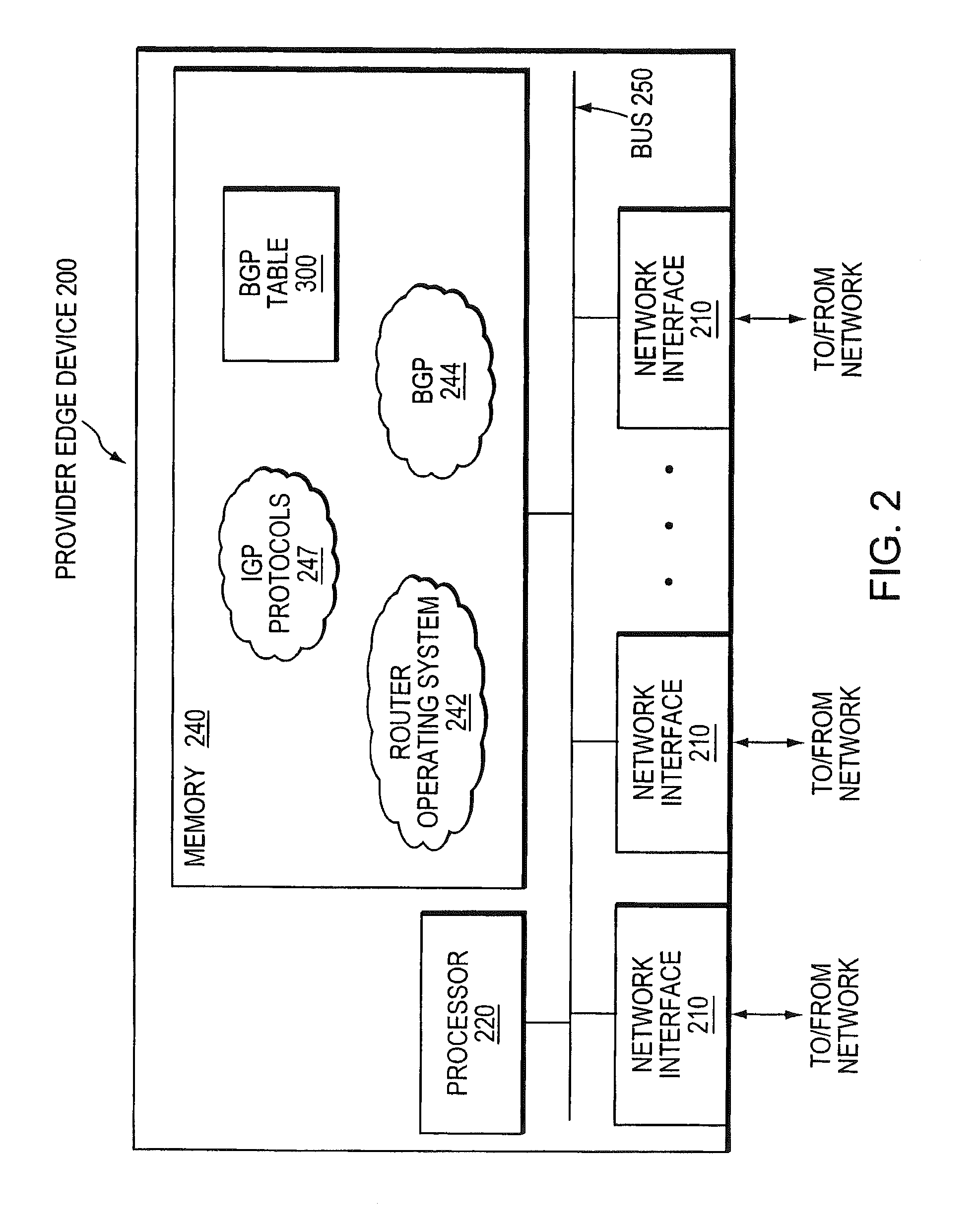
[0026]The provider network 110 includes a plurality of provider edge (PE) devices 200, such as the edge devices PE1, PE2 and PE3. The PE devices are fully meshed at the BGP level. That is, each PE device in the provider network can communicat...


PUM


Abstract

In one embodiment, a network device determines identities of each peer device in a second routing domain attached to edge devices in a first routing domain. The network device associates each address prefix reachable in the second routing domain with an identity of each peer device in the second routing domain that advertised the address prefix and with an identity of one or more edge devices in the first routing domain to which that peer device is attached. The network device determines an address prefix is associated with a same identity of a peer device in the second routing domain but with different edge devices in the first routing domain. The network device assigns the different edge devices in the first routing domain associated with the determined address prefix to a shared risk node group (SRNG).

Description

RELATED APPLICATIONS[0001]This Application is a continuation of U.S. patent application Ser. No. 11 / 101,134, titled “Dynamic Shared Risk Node Group (SRNG) Membership Discovery” and filed on Apr. 7, 2005 by Jean-Philippe Vasseur et al., the contents of which are incorporated by reference herein in their entirety.FIELD OF THE INVENTION[0002]This invention relates generally to computer networks, and, more specifically, to a technique that enables a network node to automatically identify one or more shared risk node groups (SRNG) in a computer network.BACKGROUND OF THE INVENTION[0003]A computer network is a geographically distributed collection of interconnected subnetworks, such as local area networks (LAN) that transport data between network nodes. As used herein, a network node is any device adapted to send and / or receive data in the computer network. Thus, in this context, “node” and “device” may be used interchangeably. The network topology is defined by an arrangement of network n...

Claims


Application Information

Patent Timeline
Patent Type & Authority Applications(United States)
IPC IPC(8): G06F15/173G06F15/16H04L45/02H04L45/28
CPCH04L45/02H04L45/28H04L45/04H04L45/033
Inventor VASSEUR, JEAN-PHILIPPEGUICHARD, JIMRASZUK, ROBERT
Owner CISCO TECH INC
Why Eureka
Try Eureka