

Rotatable light source device
- Summary
- Abstract
- Description
- Claims
- Application Information
AI Technical Summary
Benefits of technology
Problems solved by technology
Method used
Image

Examples
Embodiment Construction
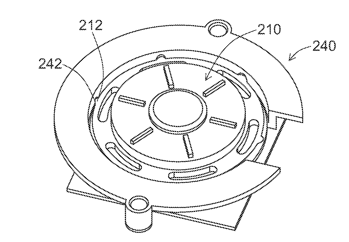
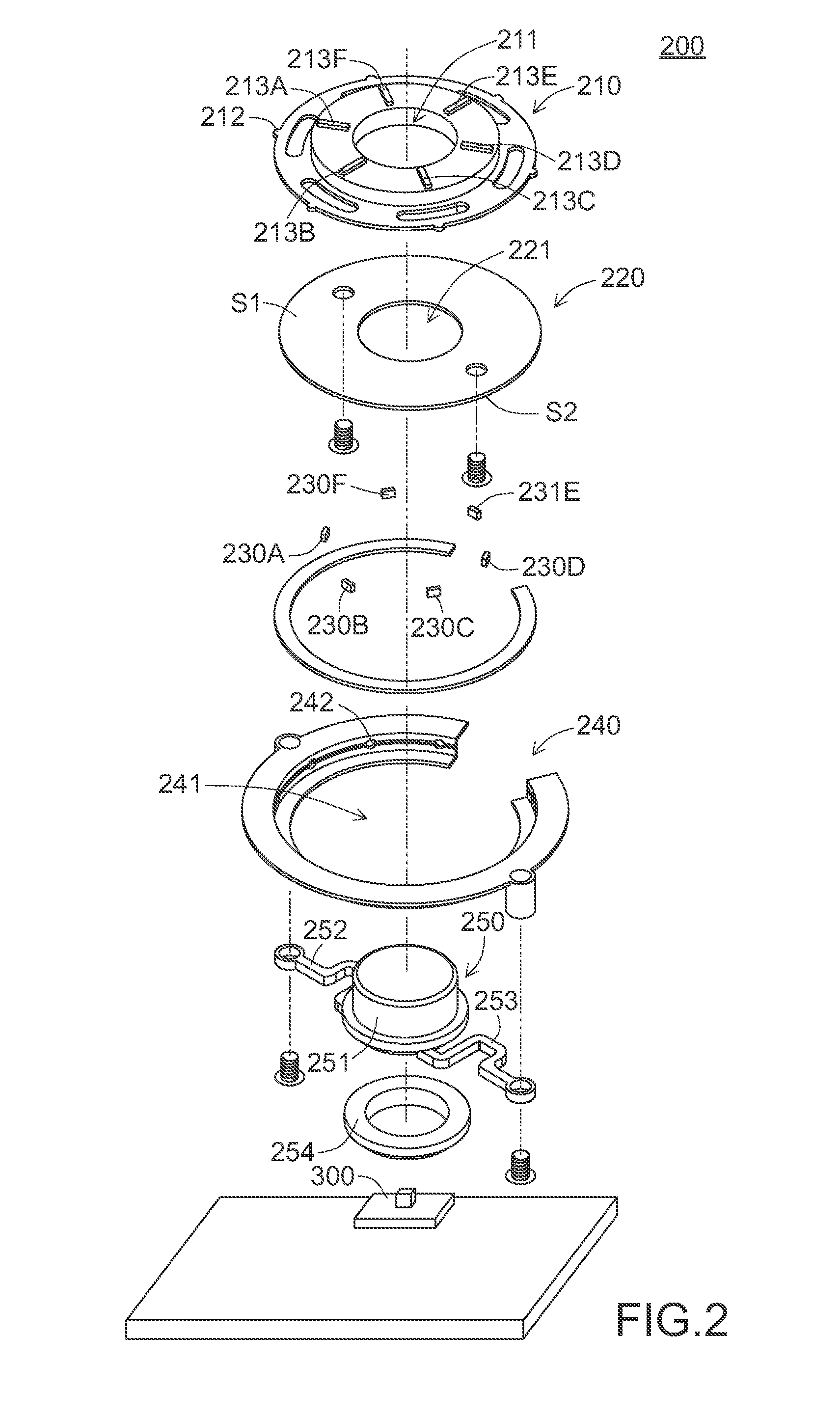
[0030]FIG. 2 is a schematic exploded view illustrating a rotatable light source device according to a first embodiment of the present invention. As shown in FIG. 2, the rotatable light source device 200 comprises an upper cover 210, a circuit board 220, plural light-emitting elements 230A, 230B, 230C, 230D, 230E and 230F, a base 240, a fixture member 250 and a push switch 300. The circuit board 220 is disposed under the upper cover 210. The circuit board 220 has an upper surface S1 and a lower surface S2. The upper surface S1 of the circuit board 220 is connected with the upper cover 210. In addition, by means of screws, the upper surface S1 of the circuit board 220 is fixed on the upper cover 210. The light-emitting elements 230A-230F are mounted on the lower surface S2 of the circuit board 220.
[0031]The base 240 has a receptacle 241 for accommodating the upper cover 210 and the circuit board 220. The fixture member 250 comprises a light-transmissible shaft 251, two fixing arms 252...
PUM
 Abstract
Description
Claims
Application Information