Electrostatically actuated device

Active Publication Date: 2021-01-28
RGT UNIV OF CALIFORNIA
View PDF0 Cites 0 Cited by
  • Summary
  • Abstract
  • Description
  • Claims
  • Application Information

AI Technical Summary

Benefits of technology

[0008]In one or more examples, such an electrostatically actuated device has relatively low fabrication costs, and consumes relatively low power, and is suitable for a wide variet

Problems solved by technology

These forces are readily controlled by applying a difference in voltage between electrodes, resulting in relatively large amounts of motion.
However, the charges trapped in the bulk and/or on the surfaces can c

Method used


Image

  • Electrostatically actuated device
  • Electrostatically actuated device
  • Electrostatically actuated device

Examples


first example

Structure

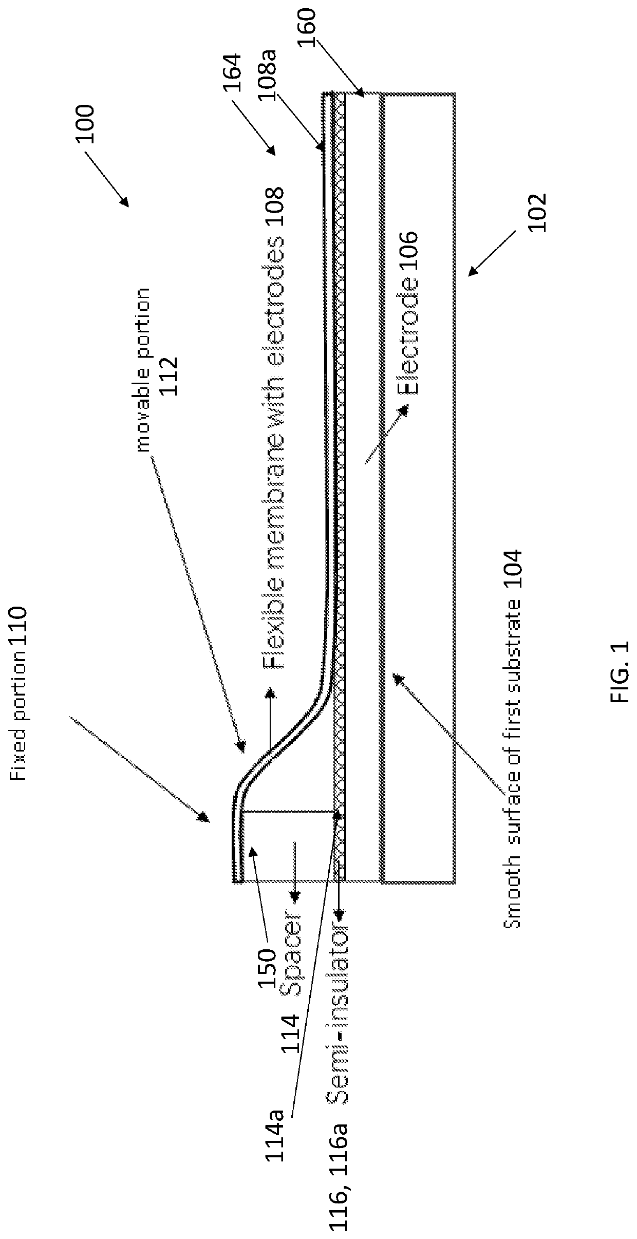
[0047]FIG. 1 illustrates an actuator device 100 driven by electrostatic forces, comprising a substrate 102 including and / or defining a smooth surface 104; a layer comprising a substrate electrode 106 on the smooth surface of the substrate; and a flexible membrane 108 overlaying the substrate electrode. The flexible membrane 108 includes a flexible electrode 108c (or flexible electrode layer 108a); a fixed portion 110; and a movable portion 112. The fixed portion is attached to an underlying surface 114a (e.g., a spacer 114) of the substrate or to a spacer 114 between the substrate 102 and the fixed portion 110. The movable portion 112 is movable with respect to the substrate electrode 106. FIG. 1 further illustrates a semi-insulator 116 (or layer 116a comprising a semi-insulator) separating the substrate electrode 106 from the flexible electrode or flexible electrode layer 108a. In one or more examples, the semi-insulator 116 is on or above the substrate electrode 106. In o...

second example

Structure

[0048]FIG. 2 illustrates an actuator device 200 driven by electrostatic forces having the structure of FIG. 2 but also further comprising a second substrate 202 (having and / or defining a second smooth surface 204); and a second layer comprising a second substrate electrode 206 on the second smooth surface of the second substrate, so that the flexible membrane 108 overlays the first substrate electrode 106 or the second substrate electrode 206 depending on the voltage differential being applied between the flexible electrode and the flexible electrode layer and the substrate electrodes. FIG. 2 further illustrates the flexible membrane further includes a second fixed portion 208 (attached to an underlying surface 208a of the second substrate or to a second spacer 210 between the second substrate and the second fixed portion). The movable portion 112 is movable with respect to the first substrate electrode 106 and the second substrate electrode 206. A second semi-insulator 212...

third example

Structure (Cooling Device)

[0049]FIG. 3 illustrates an electrostatically actuated electrocaloric cooling device 300, comprising a first substrate 302 defining or having a smooth surface 304; a first substrate electrode 306 forming a layer, or a layer 306a comprising an electrode 306, on the smooth surface of the first substrate; a second substrate 308 defining or having a smooth surface 310; and a second substrate electrode 312 forming a layer (or a layer 312a comprising an electrode 312) on the smooth surface 310 of the second substrate.

[0050]The device further includes a (e.g., two-layer) flexible electrocaloric (e.g., polymer) stack 314 including one or more polymer layers 314b and one or more (e.g., three) flexible electrode layers 314a, fixed portions 316a, 316b attached to an underlying surface of the first substrate and the second substrate, respectively, and a movable portion 318 that is movable with respect to the first substrate electrode and the second substrate electrode....


PUM


Abstract

In an embodiment of the invention, the device comprises a bottom electrode on a substrate and a top electrode on a substrate separated by a fixed distance from each other. Semi-insulator layers with proper electrical conductivity are attached to the bottom and top electrodes. Disposed between the substrates is a flexible S-shaped polymer stack having electrode layers with one end of the stack attached to the top substrate and the other end in contact with the bottom substrate. When a voltage is applied between the stack and the electrode layer on the bottom substrate, the stack is induced by electrostatic force to deflect in a rolling wave-like motion.

Description

CROSS REFERENCE TO RELATED APPLICATIONS[0001]This application claims the benefit under 35 U.S.C. Section 119(e) of co-pending and commonly-assigned U.S. Provisional Patent Application Ser. No. 62 / 647,037, filed on Mar. 23, 2018, by Qibing Pei, Rujun Ma, and Ziyang Zhang entitled “ELECTROSTATICALLY ACTUATED DEVICE”, (2018-449-1); which application is incorporated by reference herein.TECHNICAL FIELD[0002]The present invention relates to electrostatically actuated device structures, e.g., with high operation frequency.BACKGROUND OF THE INVENTION[0003]Actuated devices have led to the development of various techniques and structures for providing the force necessary to cause the desired motion. For example, microcantilevers have been used to apply rotational mechanical force to rotate micromachined springs and gears. Electromagnetic fields have been used to drive micromotors. Piezoelectric forces have also been successfully used to controllably move micromachined structures. Controlled t...

Claims


Application Information

Patent Timeline
IPC IPC(8): F25B21/04
CPCF25B21/04F25B2321/001F25B21/00Y02B30/00
Inventor PEI, QIBINGMA, RUJUNZHANG, ZIYANG
Owner RGT UNIV OF CALIFORNIA
Why Eureka
Try Eureka