Heat exchanger

Active Publication Date: 2018-08-16
LG ELECTRONICS INC
View PDF9 Cites 0 Cited by
  • Summary
  • Abstract
  • Description
  • Claims
  • Application Information

AI Technical Summary

Benefits of technology

[0039]The heat exchanger of the present invention has one or more following effects.
[0040]First, the present invention has an advantage in that condensate water can be easily moved to a pin disposed on the lower side through the condensate water discharge hole and the condensate water discharge pin.
[0041]Second, the present invention has an advantage in that it can be fabricated through a machine of a pin roll method because the condensate water discharge hole and the condensate water discharge pin are formed by cutting off and bending part of the first pin part and the second pin part.
[0042]Third, the present invention has an advantage in that a fabrication cost is low because it can be fabricated through a m

Problems solved by technology

The pin tube type heat exchanger is easily fabricated because a pin and a tube are welded, whereas the micro channel type heat exchanger has a disadvantage in that an initial investment cost according to fabrication is high because it is fabricated through brazing by inputting it into a furnace.
The conventional micro channel type heat exchanger fabricated as described above has very higher heat exchange efficiency of a refrigerant and air than the

Method used


Image

  • Heat exchanger
  • Heat exchanger
  • Heat exchanger

Examples


Example

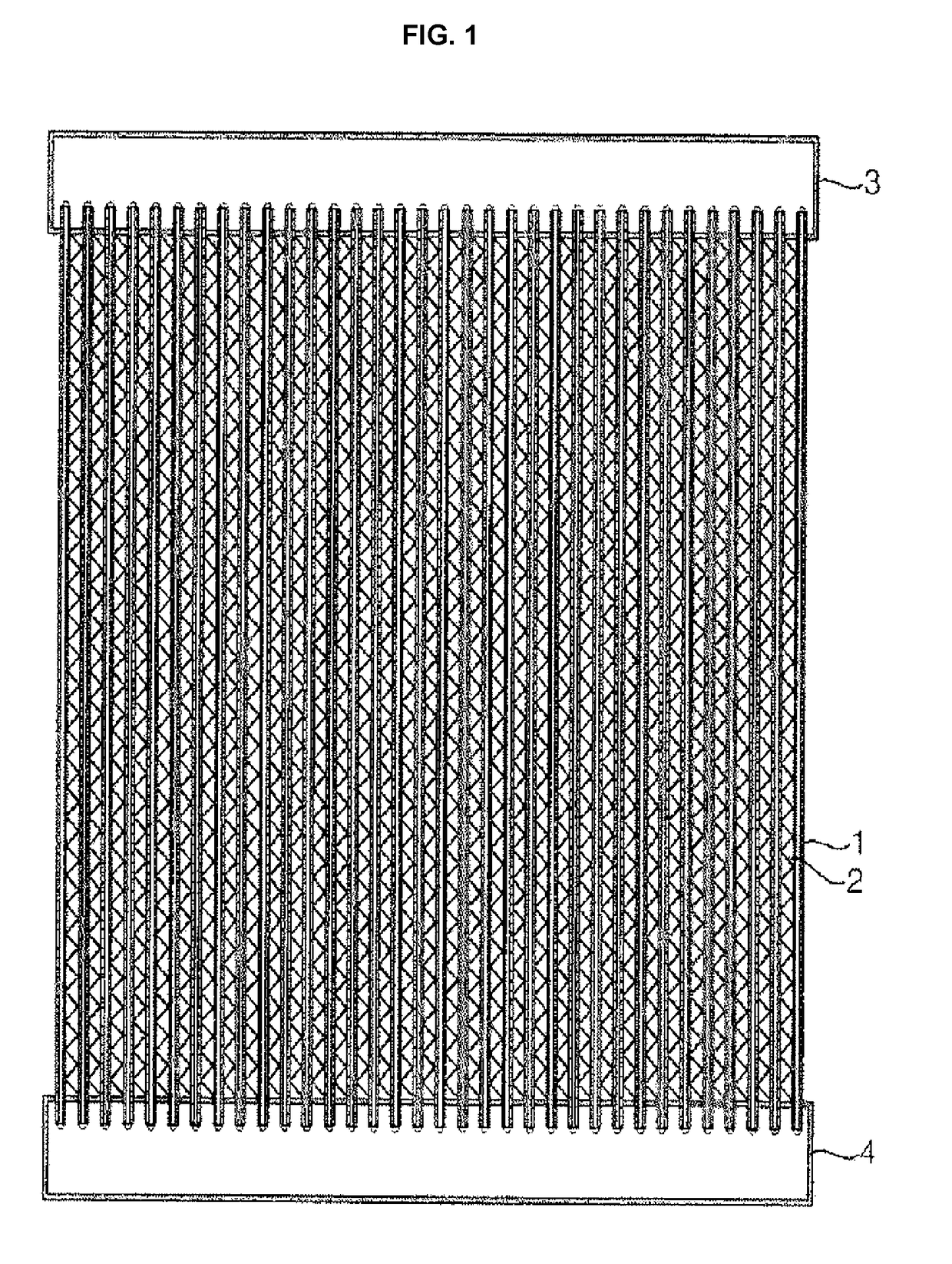
[0075]A micro channel heat exchanger according to a first embodiment is described with reference to FIGS. 2 to 5.

[0076]The micro channel type heat exchanger according to the present embodiment includes a plurality of flat tubes 10 in which a plurality of flow channels has been formed, pins 20 disposed between two flat tubes 10 and coupled to the two flat tubes 10 to conduct heat, and a first header (not shown) and a second header (not shown) assembled with both ends of the plurality of flat tubes 10 to move a refrigerant.

[0077]In the micro channel type heat exchanger, if a refrigerant is supplied to the first header, the refrigerant passes through the flat tubes 10 and moves to the second header. In contrast, if a refrigerant is supplied to the second header, the refrigerant flows to the first header.

[0078]The first header and the second header have structures widely known to those skilled in the art, and a detailed description thereof is omitted.

[0079]The flat tube 10 is formed in ...

Example

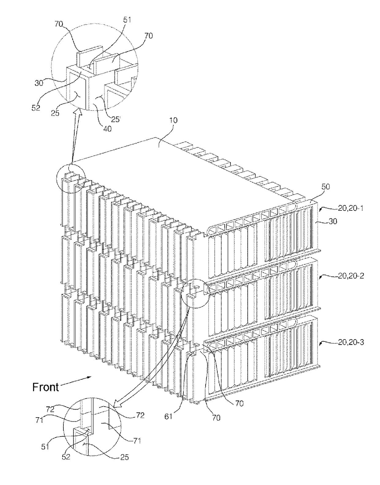
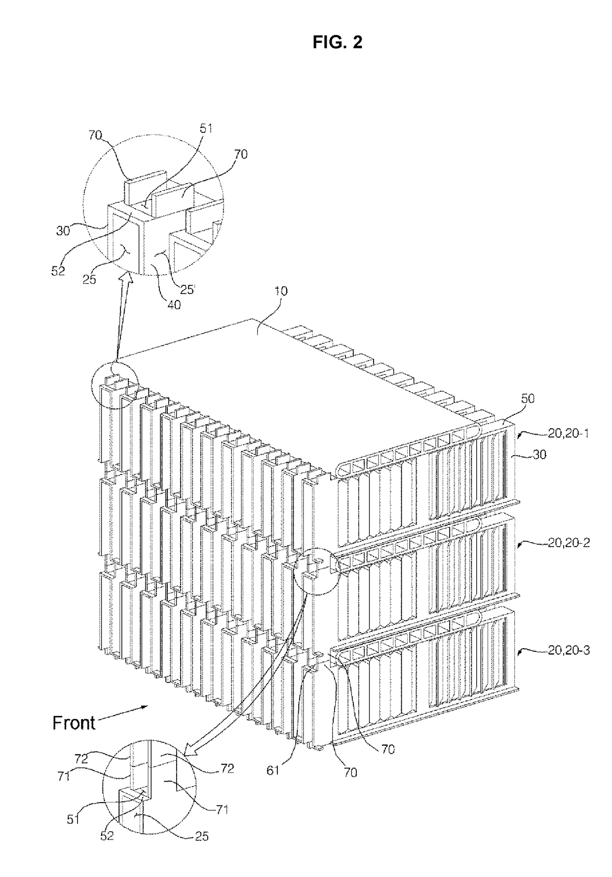
[0141]A micro channel type heat exchanger according to a second embodiment of the present invention is described with reference to FIGS. 6 to 9.

[0142]For a description, a pin 220 located at the top is defined as a first pin 220-1, a pin 220 located under the first pin 220-1 is defined as a second pin 220-2, and a pin 220 located under the second pin 220-2 is defined as a third pin 220-3.

[0143]Unlike in the first embodiment, in the pin 220 according to the present embodiment, condensate water discharge pins 271 and 272 are disposed on the front side and rear side of the flat tube 10, respectively.

[0144]The first condensate water discharge pins 271 are disposed on the front side and rear side of the flat tube 10, respectively. The first condensate water discharge pins 271 are disposed on the front side and rear side of the first bent part 50, respectively.

[0145]The second condensate water discharge pins 272 are disposed on the front side and rear side of the flat tube 10, respectively...

Example

[0153]A micro channel type heat exchanger according to a third embodiment of the present invention is described with reference to FIGS. 10 to 12.

[0154]In the present embodiment, for a description, a pin 320 located at the top is defined as a first pin 320-1, a pin 320 located under the first pin 320-1 is defined as a second pin 320-2, and a pin 320 located under the second pin 320-2 is defined as a third pin 320-3.

[0155]Unlike in the second embodiment, the pin 320 according to the present embodiment does not include the configuration of the connection part 52 forming the condensate water discharge hole.

[0156]Accordingly, the first condensate water discharge hole 51 is formed on the front side of the first bent part 50, and the front side of the first condensate water discharge hole 51 is open. The first condensate water discharge hole 51 is formed at the rear end of the first bent part 50, and the rear side of the first condensate water discharge hole 51 is open. If the connection p...


PUM


Abstract

The present invention relates to a heat exchanger comprising: flat tubes formed of a microchannel type; and first and second fins positioned at the top and bottom of the flat tubes so as to conduct the heat of the flat tubes, wherein the first and second fins are respectively provided with first and second condensate water discharge pins at the top and bottom, the second condensate water discharge pins of the first fins and the first condensate water discharge pins of the second fins come into contact, and the second condensate water discharge pins of the first fins and the first condensate water discharge pins of the second fins are disposed in a line with respect to the vertical direction, thereby having the advantage of quickly transferring condensate water formed at the top to the bottom.

Description

TECHNICAL FIELD[0001]The present invention relates to a heat exchanger and, more particularly, to a heat exchanger capable of easily discharging condensate water when it is used as an evaporator.BACKGROUND ART[0002]In general, a heat exchanger may be used as a condenser or an evaporator in a cooling cycle apparatus including a compressor, a condenser, an expansion apparatus, and an evaporator.[0003]Furthermore, the heat exchanger is disposed in a vehicle or a refrigerator and heat-exchange a refrigerant and air.[0004]The heat exchanger may be divided into a pin tube type heat exchanger and a micro channel type heat exchanger depending on its structure.[0005]The pin tube type heat exchanger is fabricated using a copper material, and the micro channel type heat exchanger is fabricated using an aluminum material.[0006]The micro channel type heat exchanger has better efficiency than the pin tube type heat exchange because a fine flow channel is formed in the micro channel type heat exch...

Claims


Application Information

Patent Timeline
IPC IPC(8): F28D1/04F28F1/02F28F1/32F28F1/42F28F17/00F28F9/013
CPCF28D1/04F28F1/025F28F1/32F28F1/42F28F17/005F28F9/013F28F1/022F28F1/128F28F2260/02
Inventor LEE, EUNGYULJUNG, SEUNGMOKIM, JUHYOKPARK, TAEGYUN
Owner LG ELECTRONICS INC
Why Eureka
Try Eureka