Air cooling architecture for network switch chassis with orthogonal midplane

a network switch and chassis technology, applied in the direction of cooling/ventilation/heating modifications, electrical apparatus casings/cabinets/drawers, instruments, etc., can solve the problems of large foot-print, inconvenient side-to-side chassis airflow, and heat generation and need to be cooled

Inactive Publication Date: 2012-05-17
ARISTA NETWORKS
View PDF24 Cites 63 Cited by
  • Summary
  • Abstract
  • Description
  • Claims
  • Application Information

AI Technical Summary

Benefits of technology

[0008]The present invention provides an improved technique for air cooling orthogonal arrays of circuit boards in network switches, while providing a compact design, redundant airflow and the ability to hot-swap line cards, fabric cards, cooling fans, power supplies and other system components without interrupting the network switch operation.

Problems solved by technology

Numerous electronic components are attached to each circuit board that consume power and therefore generate heat and need to be cooled.
A chassis with an orthogonal mid-plane creates a cooling challenge since the orientation of the two sets of circuit boards are orthogonal to each other.
However, side-to-side chassis airflow is not desirable for data centers that use cold-aisle / hot-aisle layout, which require airflow to go from the cold aisle to the hot aisle.
This type of rack requires a larger foot-print than a standard server rack and wastes valuable real estate in the data center.
However, because of the two 90 degree airflow turns, this type of chassis design wastes a large amount of space for the airflow to enter and exit the chassis.
In addition, turning the airflow direction wastes cooling energy.
For all these reasons, the front-to-rear cooling approach that takes two 90 degree turns through the chassis is not satisfactory.
One of the least reliable elements in a networking switch are the fans which move the air through the chassis to cool the active components that generate heat.
However, a typical modular networking chassis has many fans, and a data center typically has many networking switches.
Thus, the aggregate failure rates of all the fans in all the network switches within a data center can be quite high.
If such fan failures were to interrupt the throughput of the network, it would have a severe impact on the overall data center availability and the applications the data center provides.

Method used


Image

  • Air cooling architecture for network switch chassis with orthogonal midplane
  • Air cooling architecture for network switch chassis with orthogonal midplane
  • Air cooling architecture for network switch chassis with orthogonal midplane

Examples


Embodiment Construction

[0017]As used throughout this document, words such as “comprise”, “including” and “having” are intended to set forth certain items, steps, elements or aspects of something in an open-ended fashion. Unless a specific statement is made to the contrary, these words do not indicate a closed-end list to which additional things cannot be added.

[0018]In general, the designations “front”, “rear”, “left” and “right” are used here-in to designate relative positions. These designations should not be construed as absolute positions.

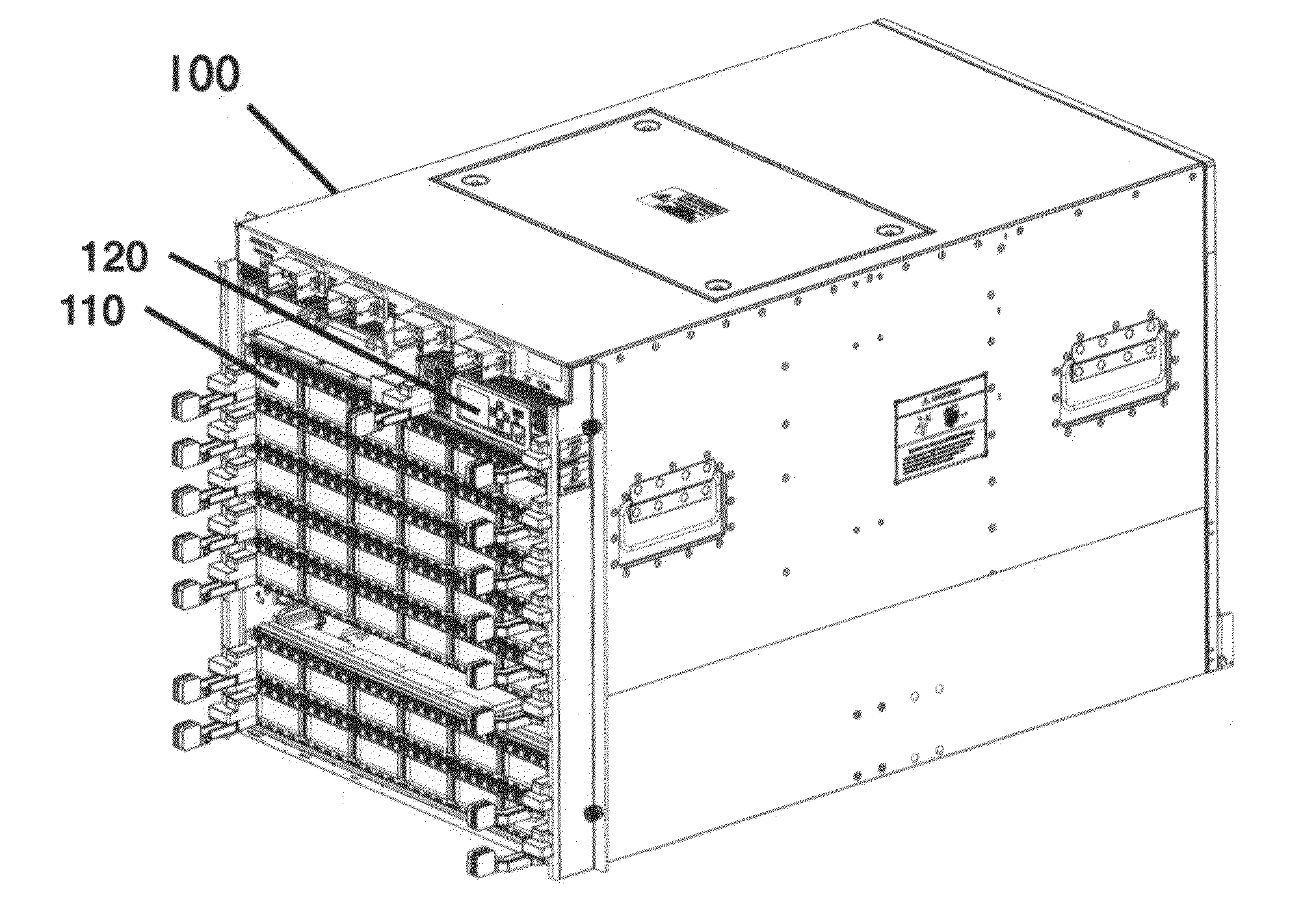
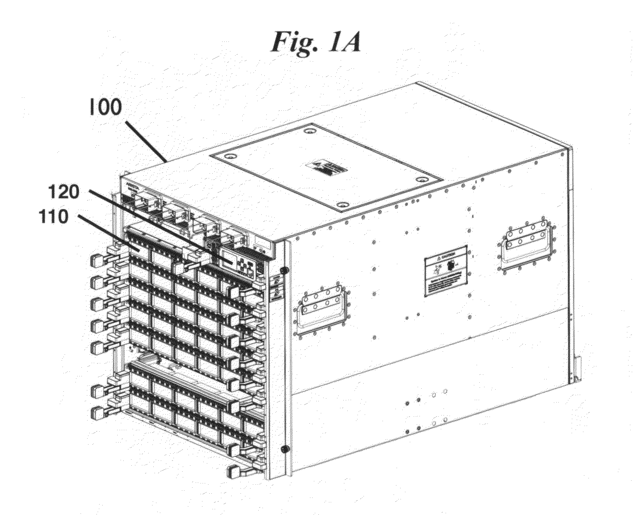
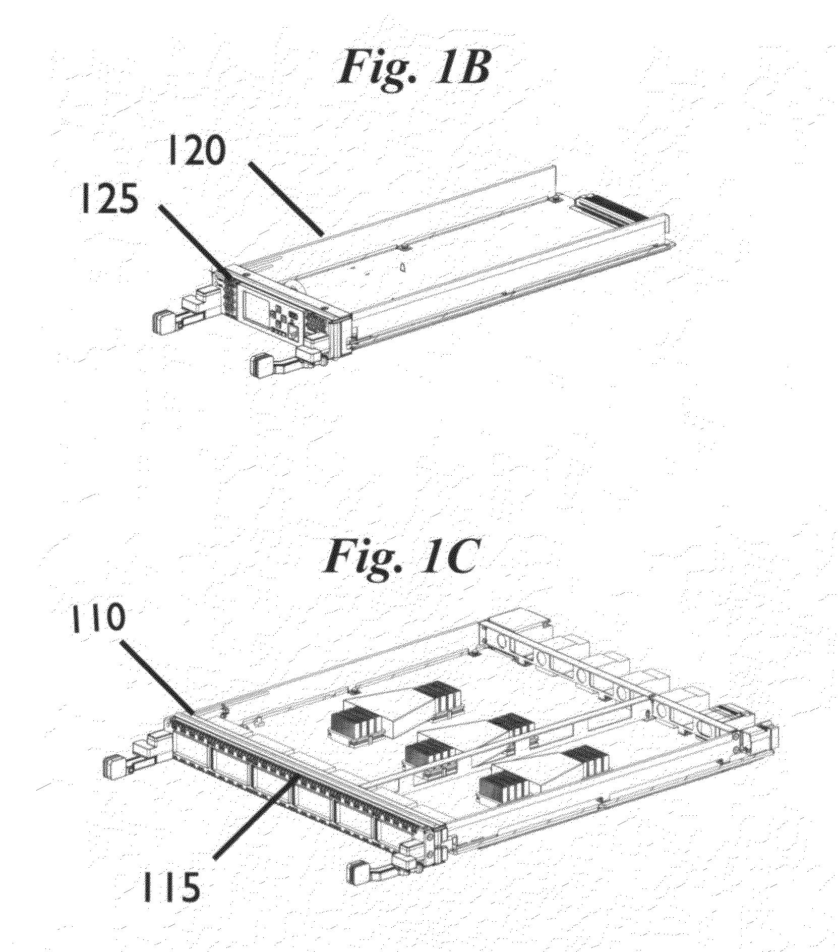
[0019]FIGS. 1A-C and 2A-C show the front and the rear views, respectively, of a network chassis 100 configured in accordance with an embodiment of the invention. As shown in FIG. 1A, the network chassis 1.00 includes a first array of parallel circuit boards 110 (FIG. 1C) plugged into a front surface of chassis 100 and, as shown in FIG. 2A, the network chassis includes a second array of parallel circuit boards 210 (FIG. 2B) plugged into the rear surface of the chassis...


PUM


Abstract

A network switch chassis provides a linear, front-to-rear air flow path for cooling first and second orthogonally oriented arrays of parallel circuit boards connected by a midplane. Air is drawn into the front of the chassis and passes in a straight path over the first array of circuit boards, through air openings in the midplane, over the second array of circuit boards, and out the rear of the chassis. Resilience against service interruption due to fan failure is achieved with multiple fans cooling each circuit board.

Description

CROSS-REFERENCE TO RELATED APPLICATIONS[0001]This application claims priority from U.S. Provisional Patent Application 61 / 414390 filed Nov. 16, 2010, which is incorporated herein by reference.FIELD OF THE INVENTION[0002]The present invention relates generally to the design of network switches. More specifically, it relates to techniques for resilient cooling in a network switch chassis with an orthogonal midplane design.BACKGROUND OF THE INVENTION[0003]Networking switches are commonly built with multiple circuit boards that plug into a common backplane that provides connectors and traces for establishing electrical connections between the different types of circuit boards that plug into the backplane. This type of chassis is also commonly called a modular network switching chassis. Numerous electronic components are attached to each circuit board that consume power and therefore generate heat and need to be cooled. The circuit boards and the backplane are generally housed in a chass...

Claims


Application Information

Patent Timeline
Patent Type & Authority Applications(United States)
IPC IPC(8): G06F1/20
CPCH05K7/20572G06F1/20
Inventor BECHTOLSHEIM, ANDREAS
Owner ARISTA NETWORKS
Why Eureka
Try Eureka