Street lighting device

a street lighting and device technology, applied in the direction of lighting and heating equipment, semiconductor devices for light sources, instruments, etc., can solve the problem that the lamp unit can only illuminate a partial area, and achieve the effect of simple fashion

Inactive Publication Date: 2012-05-17
HELLA KG HUECK & CO
View PDF2 Cites 79 Cited by
  • Summary
  • Abstract
  • Description
  • Claims
  • Application Information

AI Technical Summary

Benefits of technology

[0007]The embodiments are based on the object of developing further the design of a lighting device in a manner whereby, in a simple fashion and as needed, a predefined light distribution is achieved for the homogeneous illumination of an area.

Problems solved by technology

However, the lamp units can only serve to illuminate a partial area of a street section that is to be lit.

Method used


Image

  • Street lighting device
  • Street lighting device
  • Street lighting device

Examples


first embodiment

[0034]The light modules preferably are of a linear or elongated form and extend on the same, common plane of installation. For example, the light modules may be arranged in a manner whereby the lighting device is of a frame-, line-, star- or cross-shaped configuration. In a first embodiment the light modules feature a number of lamp units 1 row-mounted on a common support in a recess of the housing. The support and the array of lamp units 1 of a light module (for instance eight light modules) are closed off by a common transparent cover pane.

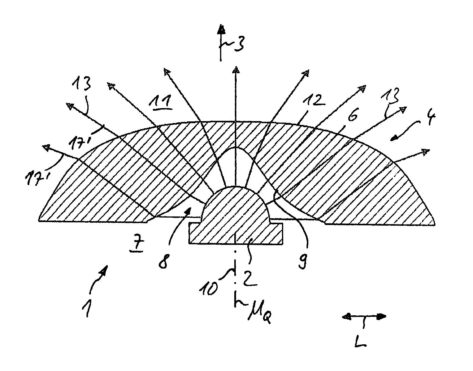
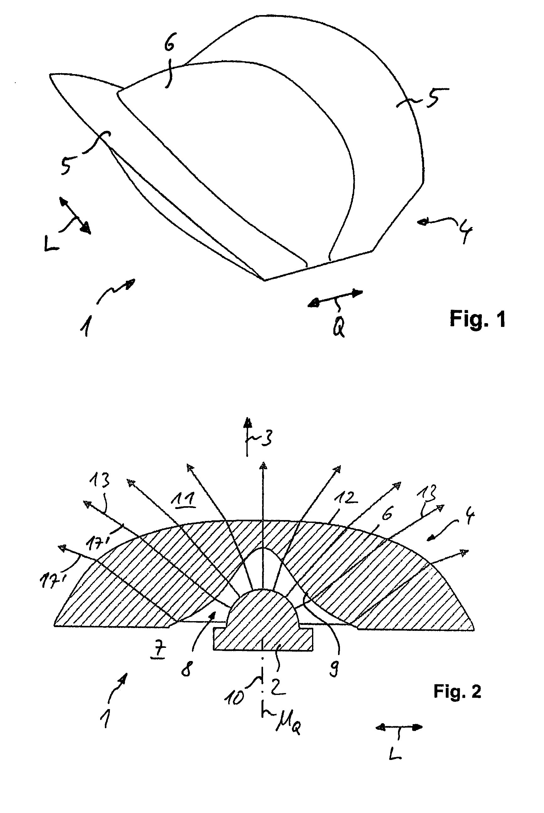
[0035]The lamp unit 1 essentially includes a light source 2 in the form of an LED chip and, positioned in the direction and in front of the main emission 3, a lens 4.

[0036]Lens 4 preferably is conchiform or has a batwing-shaped cross section and features two longitudinal side sections 5 in opposing positions relative to the longitudinal central plane ML, as well as a central section 6 connecting the longitudinal side sections 5. In an embodiment...

second embodiment

[0049]Another embodiment, shown in FIGS. 11 to 13, employs a lamp unit 31 which, like lamp unit 21 in the second embodiment, features longitudinal side sections 33, 34 asymmetrically configured in the transverse direction Q. The first longitudinal side section 33 is shaped as an ascending lateral wing that is essentially positioned on a first side of a longitudinal central plane ML of lens 32. A second longitudinal side section 34 is in the form of a descending lateral wing positioned on the opposite side of the longitudinal central plane ML.

[0050]The ascending lateral wing 33 and the descending lateral wing 34 are connected via a central section 35 which extends essentially in an area near the longitudinal central plane ML.

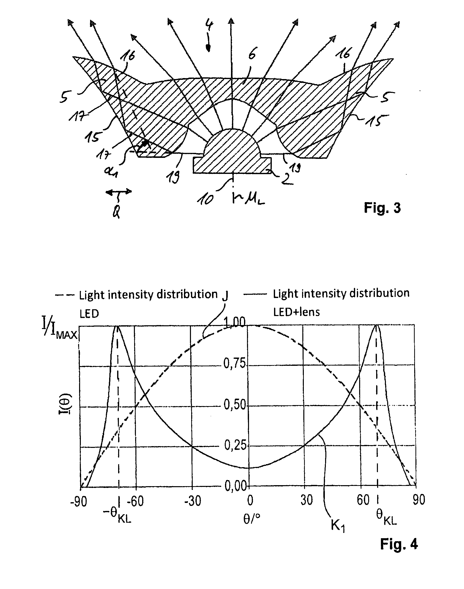
[0051]The ascending lateral wing 33 features an outward-arched lightentrance surface 36 which refracts light rays 37 emitted by the light source 2 essentially in the direction of a steeply extending lateral surface 38 which totally reflects them in a manner where...


PUM


Abstract

A lighting device for streets, paths, and the like, includes a lighting unit containing a lighting element and a lens arranged in front of the lighting element in the main emission direction to produce a specified light distribution characteristic. The lens includes a light entrance surface on a light entrance side facing the lighting element and a light exit surface on a light exit side facing away from the lighting element, at which surfaces the light is refracted. The light entrance surface and/or the light exit surface of the lens is shaped in a direction transverse to the optical axis of the lighting element in such a way that the luminous intensity of the coupled out light, starting from a center plane that intersects with the optical axis, rises with an increasing emission angle from the optical axis at least partially according to a tangent function.

Description

PRIORITY CLAIM[0001]The present application is a continuation of a currently pending International Patent Application No. PCT / EP2010 / 056453 filed on May 11, 2010, which designates the United States and claims priority from and benefit of the German Patent Application No. 10 2009 021 182.9 filed on 13 May 2009. The present application claims priority from and benefit of the aforementioned International Patent Application and, through this International Patent Application, a priority from and benefit of the above mentioned German Patent Application. Disclosure of each of the above-mentioned patent applications is incorporated herein by reference in its entirety.BACKGROUND OF THE INVENTION[0002]1. Field of the Invention[0003]The invention relates to a lighting device for streets, pathways and the like, with a lamp unit including a light source and, positioned in front of the light source in the main emission direction, a lens configured to generate a predefined light distribution patte...

Claims


Application Information

Patent Timeline
Patent Type & Authority Applications(United States)
IPC IPC(8): F21V13/04
CPCF21V5/04F21V5/08F21V7/0091G02B19/0061F21Y2101/02Y02B20/72G02B19/0028F21W2131/103F21Y2115/10
Inventor MOELLER, DENNIS
Owner HELLA KG HUECK & CO
Why Eureka
Try Eureka