Transport device for objects in packaging machines

a technology for transporting devices and objects, which is applied in the direction of paper/cardboard containers, charge manipulation, furnaces, etc., can solve the problem that the known adjusting mechanism for adapting to the width of various folding boxes is relatively expensiv

Inactive Publication Date: 2004-02-05
ROBERT BOSCH GMBH
View PDF15 Cites 18 Cited by
  • Summary
  • Abstract
  • Description
  • Claims
  • Application Information

AI Technical Summary

Problems solved by technology

Due to its embodiment as a hub and a hollow shaft disposed concentrically around the hub, the known adjusting mechanism for adapting to various folding box wid

Method used


Image

  • Transport device for objects in packaging machines
  • Transport device for objects in packaging machines
  • Transport device for objects in packaging machines

Examples


Embodiment Construction

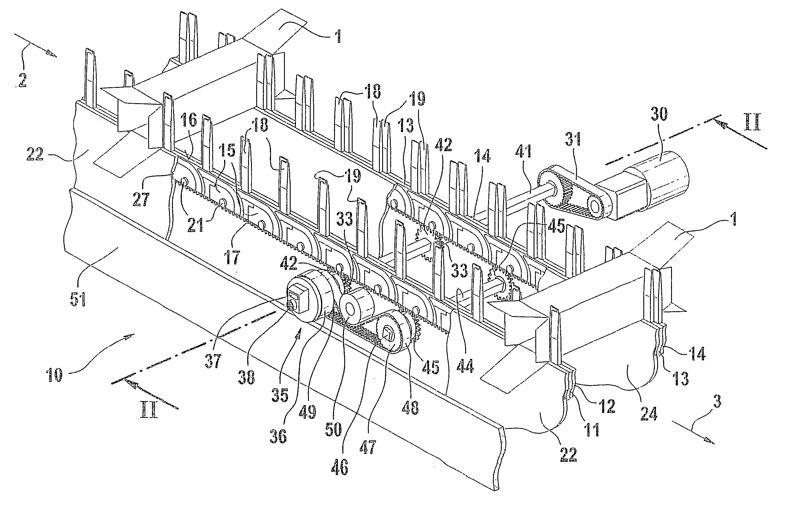
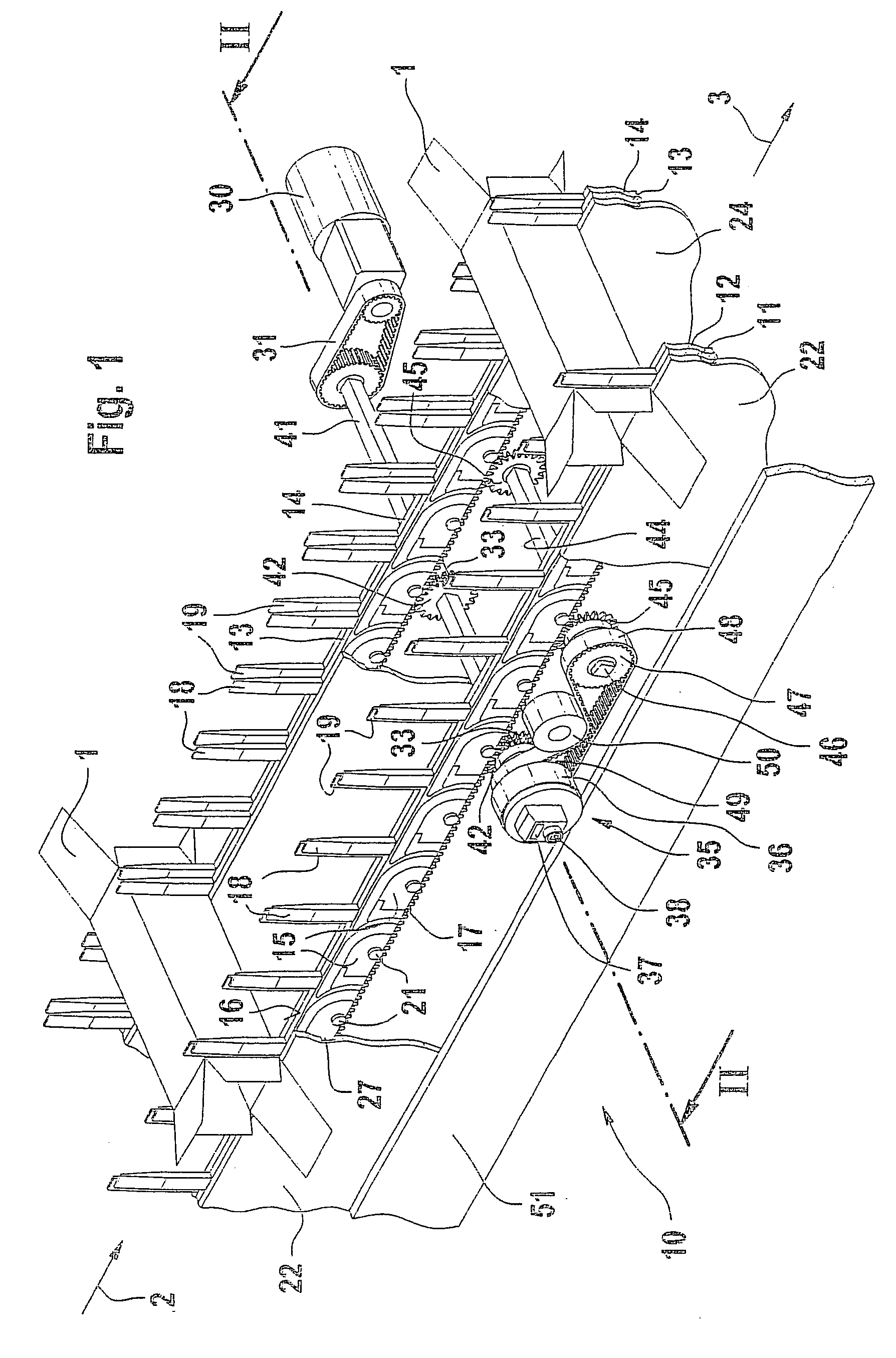
[0007] The conveyor apparatus 10 depicted in the drawings is used to transport folding boxes 1 inside a boxing machine. A transfer device, not shown, introduces the folding boxes 1 into the conveyor apparatus 10 in an infeed region 2 and the conveyor apparatus 10 continuously conveys them in the transport direction 3. During transport, a packaging product, in particular a blister strip, is inserted into the folding boxes 1. A boxing machine of this kind has been disclosed, for example, by DE 44 16 891 A1 and the transfer of folding boxes into a conveyor apparatus of this generic type has been disclosed, for example, in DE 199 20 495 A1. Neither the boxing machine nor the transfer device are essential to the invention and are therefore not discussed further.

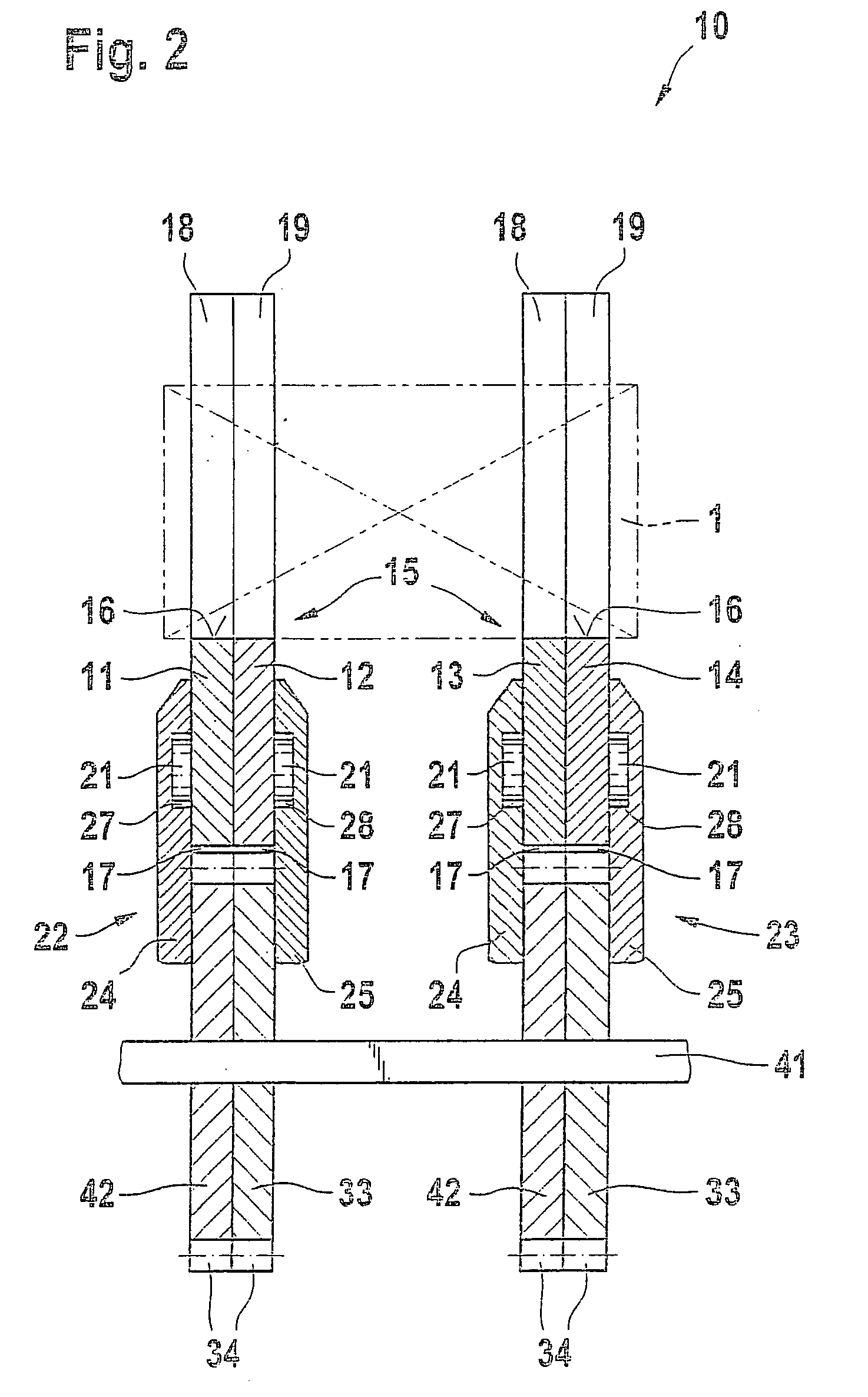
[0008] The conveyor apparatus 10, whose principle design has already been described in DE 197 31 084 A1, has a total of four parallel conveyor chains 11 to 14. Of the conveyor chains 11 to 14, two conveyor chains 11, 12 and 13, 14...


PUM


Abstract

A conveyor apparatus (10) for folding boxes (1) in a boxing machine has conveyor chains (11 to 14). The conveyor chains (11 to 14) are respectively supported in pairs in a guide rail (22, 23). The conveyor chains (11 to 14) have pusher lugs (18, 19) attached to them, between which the folding boxes (1) are contained in a positively engaging fashion. In order to permit a simple adjustment of the conveyor apparatus (10) with regard to different folding box widths and folding box lengths, the conveyor chains (11 to 14) are respectively coupled to cross sectionally polygonal shafts (41, 44). Whereas the format adaptation to different folding box widths is permitted by means of a self-locking adjusting mechanism (35), for a simple format adaptation in terms of the folding box length, according to the invention it is necessary that the gears (42, 45) that are operationally connected to the one guide rail (23) be disposed on the respective shaft (41, 44) in a rotationally fixed, but movable fashion.

Description

PRIOR ART[0001] The invention relates to a conveyor apparatus for items in packaging machines as generically defined by the preamble to claim 1, of the kind known from EP 0 485 762 B1. In the known conveyor apparatus for folding boxes, the pusher lugs are disposed on endlessly revolving conveyor chains. In the two turnaround points, the conveyor chains are supported on chain wheels, which are in turn connected to a hub and to a hollow shaft disposed concentric to the hub. The angular position of the one hub in relation to its hollow shaft can be adjusted and fixed by means of a self-locking mechanism in order to permit a format adaptation with regard to the folding box width. In addition, the two hubs are connected to each other by means of a common support whose position can be adjusted lateral to a rear frame wall in order to thus permit an adaptation with regard to various folding box lengths. Due to its embodiment as a hub and a hollow shaft disposed concentrically around the hu...

Claims


Application Information

Patent Timeline
IPC IPC(8): B65B43/52B65B59/00B65G17/26B65G21/10
CPCB65B43/52B65G2201/02B65G17/26B65B59/00B65B59/003B65B59/005
Inventor WIEDUWILT, ULRICHZELLER, JOHANN
Owner ROBERT BOSCH GMBH
Why Eureka
Try Eureka