Lightweight cable lock

a light-weight, cable-type technology, applied in the field of cable locks, can solve the problems of increasing the weight of the padlock, rigid structure, length and diameter of the cable, and reducing the practicality or usability of securing the locker

Inactive Publication Date: 2008-08-19
RAEMISCH RICHARD +1
View PDF19 Cites 17 Cited by
  • Summary
  • Abstract
  • Description
  • Claims
  • Application Information

AI Technical Summary

Benefits of technology

[0009]The present invention summarized is a locking device consisting of a flexible cable of small diameter and short length, attached at one end to a locking mechanism of a combination or permutation type capable of being engineered smaller and lighter than the combination locking mechanisms typically found in prior art cable bicycle locks. The other cable end is attached to a key designed to be received and secured into the locking mechanism. The key and locking mechanism are fabricated from a lightweight material, such as aluminum or titanium, and preferably in a relatively simple mechanical fashion to ensure light weight, while retaining strength, security, and reliability. The cable is made of a flexible material of high tensile strength that is cut-resistant, such as braided or twisted steel strands, as is well known in the art, and may be coated with a durable plastic sheath such as vinyl or PVC to further protect the cable. Additionally, the locking mechanism is designed to accept a master key, which enables the administrator of an institution that the locking device is ideally suited for to unlock any lock on the premises without needing to know each individual lock's unique combination.

Problems solved by technology

The locks most commonly employed at present are constructed primarily from hardened steel, which increases the weight of the padlocks, and results in a rigid structure.
This poses a security problem itself: the relatively heavy weight and rigid structure of the locks allows them to be effectively used as weapons by residents, either as a projectile or by placing the lock inside a sock to form a makeshift bludgeon.
The length and diameter of these cables renders them heavy and typically impractical or unusable for securing lockers and other containers in institutional settings such as prisons, schools, and hospitals.
Such locks may have a significant length of retractable cable, which poses its own danger in an institutional setting as a weapon.
Furthermore, the plastic bodies of these locks are not usually impact or tamper resistant, which diminishes their security.
However, the padlock still possesses a rigid structure by virtue of its hardened steel and dense plastic structure, which increases the risk of injury if the lock is thrown.
It also is key-operated, which present the added problem of keys that secured residents have to keep, with the risks of loss or theft.

Method used


Image

  • Lightweight cable lock
  • Lightweight cable lock
  • Lightweight cable lock

Examples


Embodiment Construction

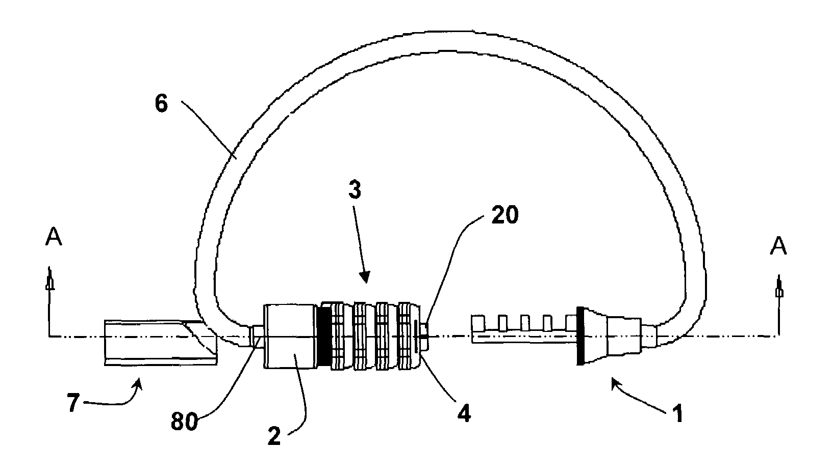
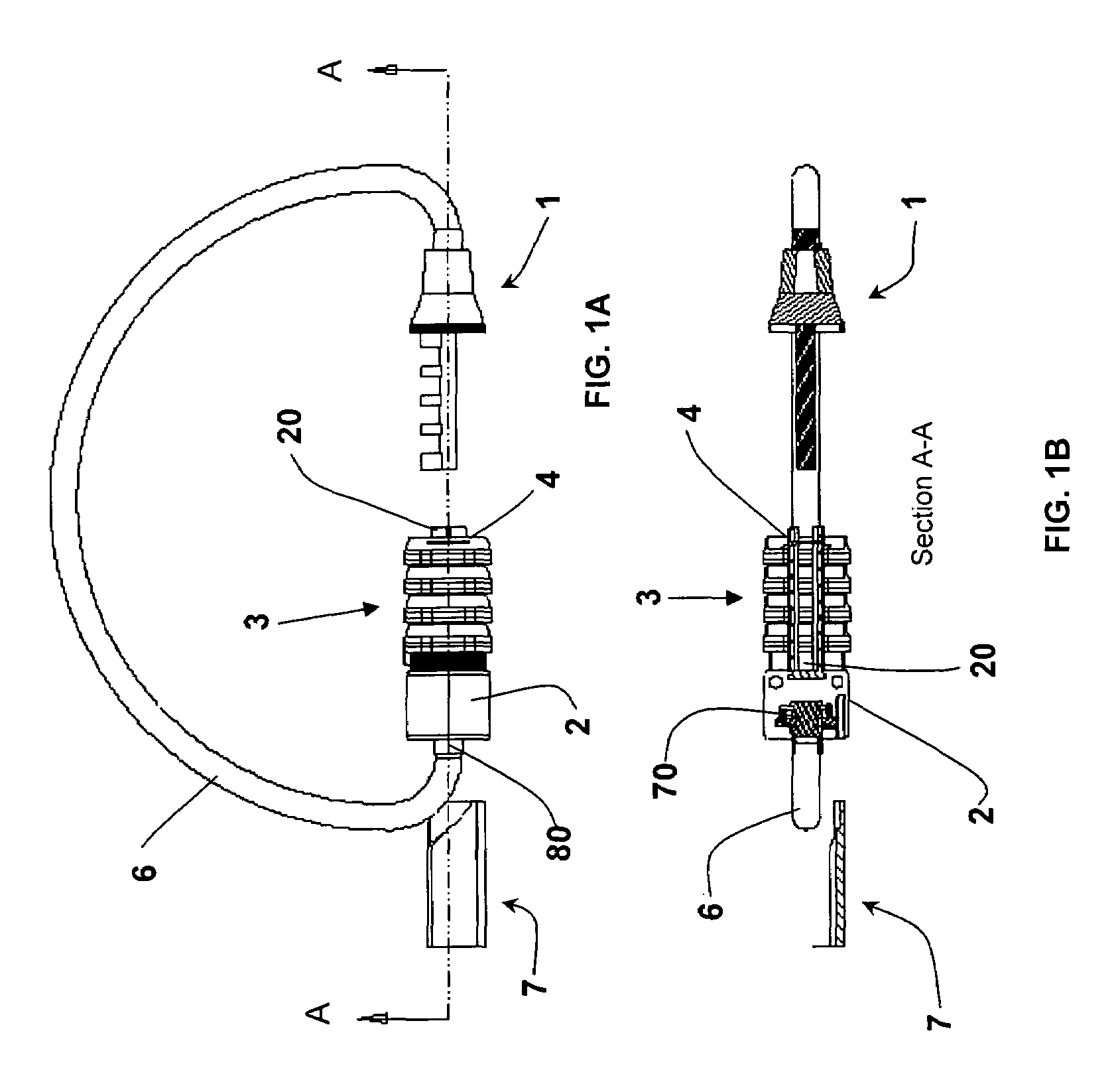
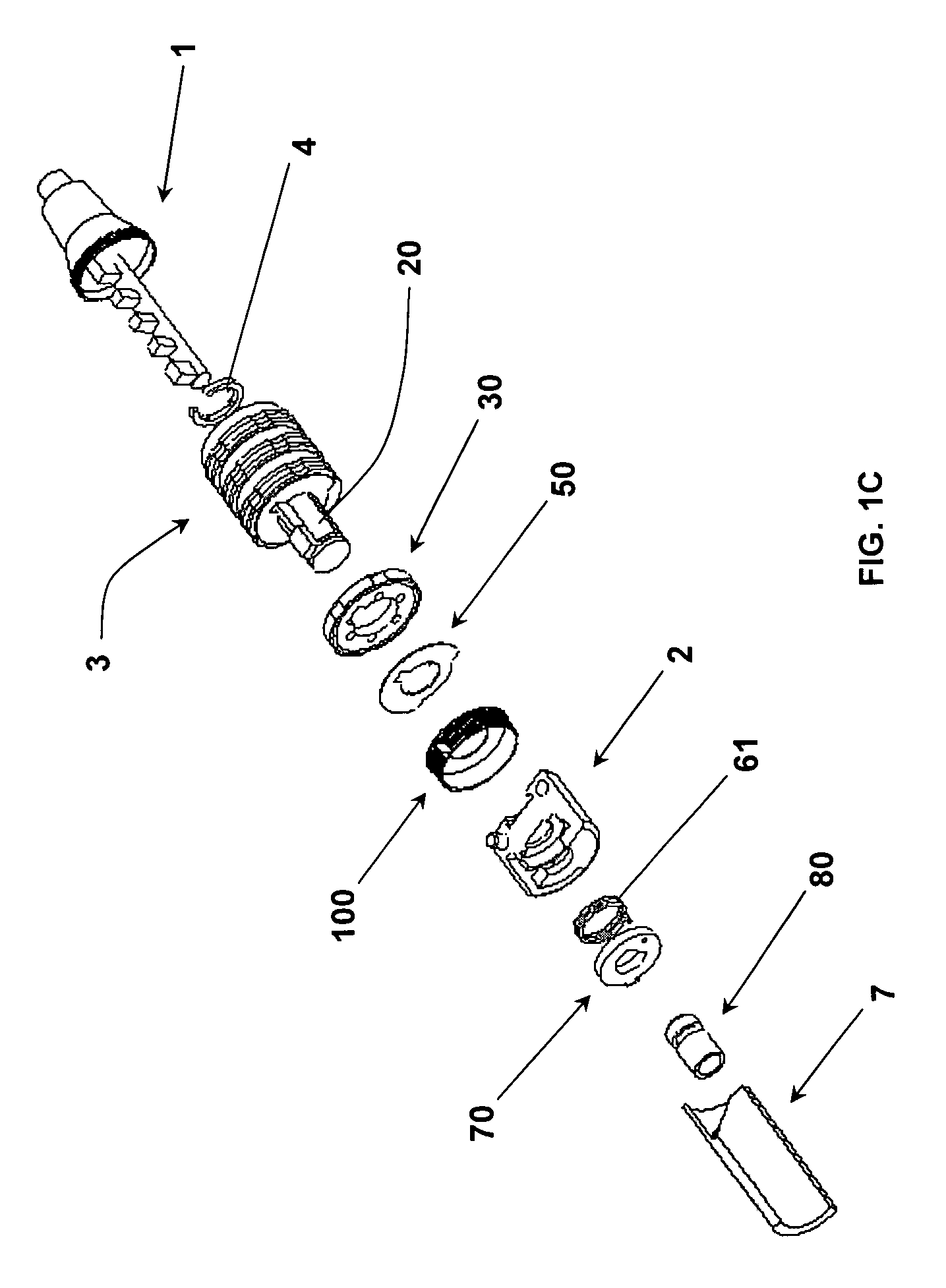
[0025]Referring to the figures, the preferred embodiment is showed in FIGS. 1A-C. The lock consists of a cable 6, which is permanently attached at one end to a key 1. The other end of the cable 6 is attached to a lock core housing 2, which in turn holds a hollow core shaft 20 in place. A lock assembly 3, formed from a plurality of numerical dials 30 interleaved with an equal number of tabbed washers 50, is fitted onto the shaft 20. The lock assembly 3 is held in place on the shaft 20 by affixing a retaining clip 4 onto the end of the shaft 20 distal from the core housing 2. The cable 6 is attached to the key 1 by fastening means that are well known in the art. The cable 6 is attached to the core housing 2 by inserting a swage key 80, which is permanently affixed to the end of the cable 6, into the end of the core housing 2 where a securing mechanism housed therein locks the cable 6 into place. The cable 6 may be removed by inserting the master unlock key 7 into the end of the core h...


PUM


Abstract

A cable padlock having a thin flexible cable, with a key attached to one cable end and a locking mechanism for receiving and securing the key attached to the other cable end, preferably of a combination or permutation type. The key and locking mechanism are constructed of lightweight materials such as aluminum, providing for a lightweight, compact, and potentially inexpensive padlock. A mechanism for detaching the cable from the locking mechanism by application of a master key is provided to allow an administrator of a facility utilizing a number of the locks to remove each lock without needing to lookup each lock's unique combination. The lock is accordingly useful in prisons, institutions, and other secured facilities where there are concerns that a traditional heavier lock could be used as a makeshift weapon.

Description

STATEMENT REGARDING FEDERALLY SPONSORED RESEARCH OR DEVELOPMENT[0001]Not applicable.BACKGROUND OF THE INVENTION[0002]1. Field of the Invention[0003]The present invention relates to cable locks, and particularly to cable locks used in secure facilities where there is a risk of residents utilizing heavy, portable objects as weapons.[0004]2. Description of the Prior Art[0005]Secure institutions such as prisons, schools, and hospitals often have means for residents to store personal property, such as lockers, storage cabinets, or foot lockers. These storage facilities are typically secured by using a padlock of some sort, operable either by key or combination. The locks most commonly employed at present are constructed primarily from hardened steel, which increases the weight of the padlocks, and results in a rigid structure. One popular model weighs close to six ounces despite being less than three inches in length. This poses a security problem itself: the relatively heavy weight and ...

Claims


Application Information

Patent Timeline
Patent Type & Authority Patents(United States)
IPC IPC(8): E05B37/02
CPCE05B37/0034E05B37/025E05B67/003Y10T70/7305Y10T70/483Y10T70/435
Inventor RAEMISCH, RICHARDROLOFF, ANDREA
Owner RAEMISCH RICHARD
Why Eureka
Try Eureka