Cervical plating system

a technology of cervical plate and screw, applied in the field of cervical plate, can solve the problems of inability to securely fix the fastening screw, limited stability and reliability of the mechanism for preventing the screw from being dislodged in the related art, and death of patients, so as to achieve more stability

Inactive Publication Date: 2012-05-17
MEDISOURCEPLUS
View PDF1 Cites 15 Cited by
  • Summary
  • Abstract
  • Description
  • Claims
  • Application Information

AI Technical Summary

Benefits of technology

[0031]According to embodiments of the invention, the screw locking member is disposed adjacent to the fastening hole, and is provided along the circumference of the fastening hole such that the screw locking member can rotate between the first position, in which the fastening hole is open, and the second position, in which the fastening hole is at least partially closed. Accordingly, it is possible to more stably and reliably prevent the fastening screw from being dislodged from the cervical plate in the state in which the cervical plating system is implanted into the human body.
[0032]In addition, the screw position fixing member is fitted into the fastening hole such that it fixedly surrounds the fastening screw, and is coupled to the screw locking member. Accordingly, it is possible to prevent the phenomenon in which the fastening between a vertebra and a screw becomes loose so that the vertebra is not stably fixed in the event that the fastening screw is shaken, even if the fastening screw is not completely dislodged from the cervical plate.

Problems solved by technology

Here, when the vertebral fixing device is implanted into the human body, it can be fatal to the patient if a screw becomes dislodged from the cervical plate.
However, since the auxiliary screws, which fasten the auxiliary plate to the cervical plate, gradually become loose such that they can become dislodged from the cervical plate, the mechanism for preventing the screws from being dislodged in the related art has limited stability and reliability.
In addition, in the state in which the vertebral fixing device is implanted in the human body, even if the fastening screw is not completely dislodged from the cervical plate, the fastening between the vertebrae and the screws may become loose by the influence of vibration from the voice of the patient or the like, so that the fastening screw becomes loose and is not securely fixed.
This phenomenon acts as a factor that hinders stable fixing of the vertebrae, and in particular, becomes severe if the fastening screws are fastened in a position in which they are inclined at a predetermined fastening angle instead of being vertically fastened to the vertebrae.

Method used


Image

  • Cervical plating system
  • Cervical plating system
  • Cervical plating system

Examples


Embodiment Construction

[0038]Advantages of the present invention and the operation thereof as well as objects to be realized by the present invention can be more apparent from the following description taken in conjunction with the accompanying drawings, in which exemplary embodiments of the invention are shown.

[0039]Reference will now be made in detail to various embodiments of the present invention, examples of which are illustrated in the accompanying drawings and described below. In the following description of the present invention, detailed descriptions of known functions and components incorporated herein will be omitted when it may make the subject matter of the present invention rather unclear.

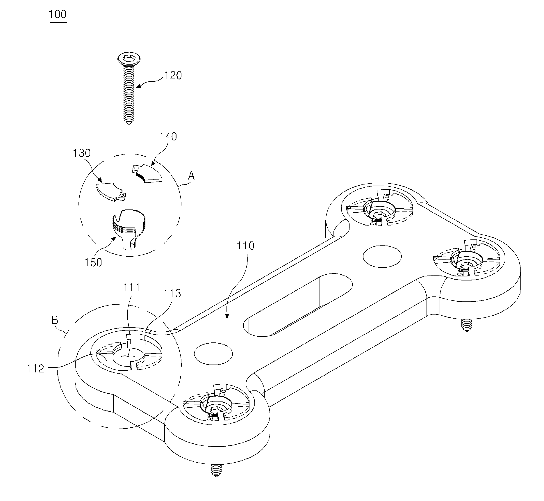
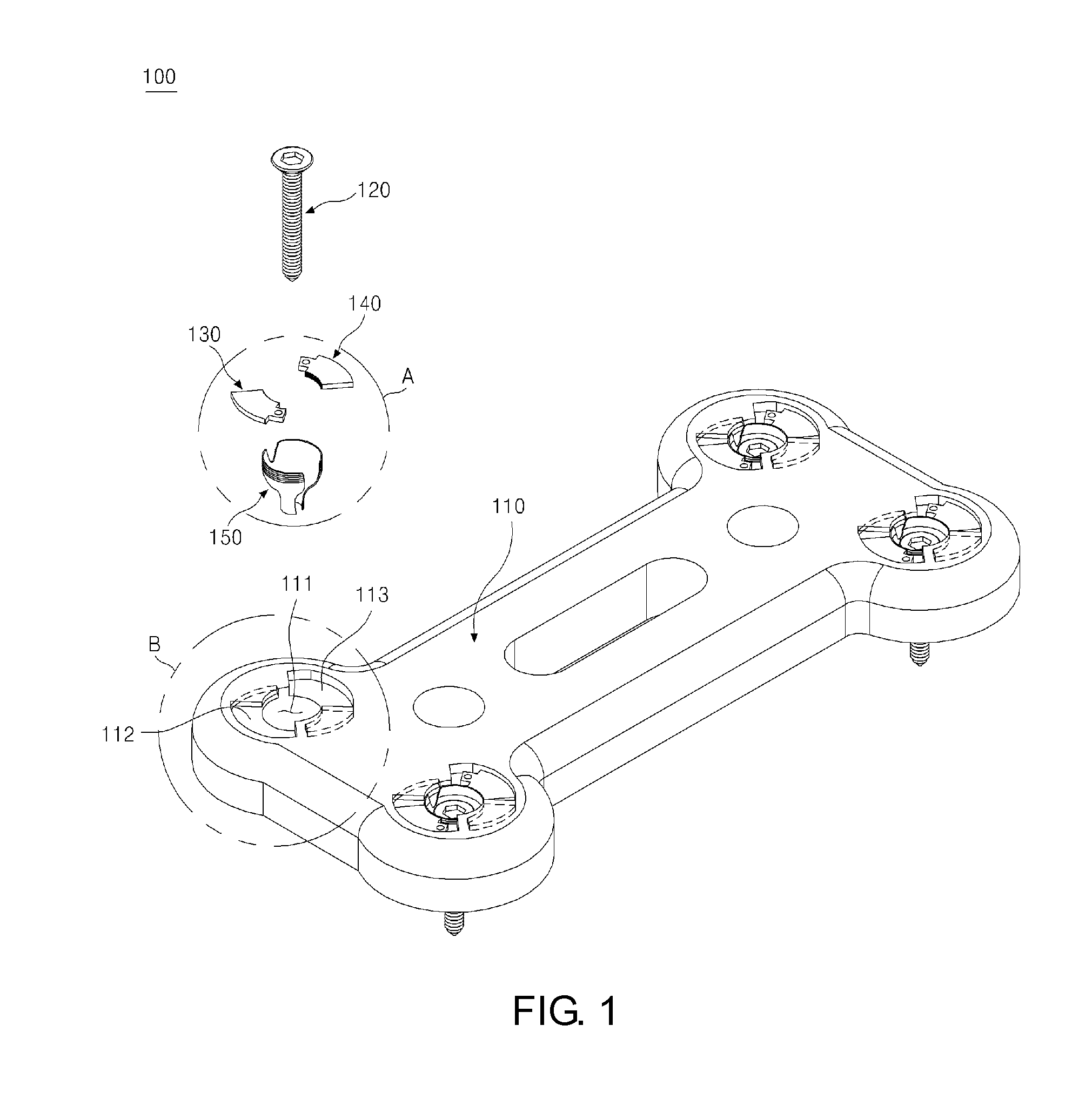
[0040]FIG. 1 is a perspective view showing a cervical plating system according to an exemplary embodiment of the invention.

[0041]Referring to FIG. 1, the cervical plating system 100 of this embodiment includes a cervical plate 110, fastening screws 120, and screw locking members 130 and 140. The cervical pl...


PUM


Abstract

A cervical plating system for fixedly connecting two or more vertebrae to each other includes a cervical plate having a fastening hole, the fastening hole penetrating the cervical plate, a fastening screw fitted into the fastening hole in the cervical plate, and a screw locking member disposed adjacent to the fastening hole. The screw locking member is rotatable along the circumference of the fastening hole between a first position, in which it opens the fastening hole, and a second position, in which it at least partially closes the fastening hole.

Description

CROSS REFERENCE TO RELATED APPLICATION[0001]The present application claims priority from Korean Patent Application Number 10-2010-0112395 filed on Nov. 12, 2010, the entire contents of which application are incorporated herein for all purposes by this reference.BACKGROUND OF THE INVENTION[0002]1. Field of the Invention[0003]The present invention relates to a cervical plating system, and more particularly, to a structure that prevents a fastening screw from being dislodged and fixes the position of the fastening screw in a cervical plating system, which fixedly connects two or more vertebrae to each other.[0004]2. Description of Related Art[0005]Operations and manipulation for treating vertebrae having an affliction, such as intervertebral disk disorders, spinal disc herniation, fractured or dislocated vertebrae, or cervical spondylotic myelopathy, generally include a process of fixing vertebrae by connecting them to each other so that they do not move. In order to fixedly connect tw...

Claims


Application Information

Patent Timeline
Patent Type & Authority Applications(United States)
IPC IPC(8): A61B17/70
CPCA61B17/7059A61B17/8057A61B17/8047
Inventor AHN, SAE YOUNGKWON, HYUN HWA
Owner MEDISOURCEPLUS
Why Eureka
Try Eureka