MEMS device with improved spring system

a technology of spring system and mems force sensor, which is applied in the field of springs to achieve the effects of reducing the cross-axis sensitivity of a mems force sensor, less sensitive to fabrication imperfections, and minimizing the response to rotation

Active Publication Date: 2012-05-24
INVENSENSE
View PDF39 Cites 28 Cited by
  • Summary
  • Abstract
  • Description
  • Claims
  • Application Information

AI Technical Summary

Benefits of technology

[0007]A system and method in accordance with an embodiment reduces the cross-axis sensitivity of a MEMS force sensor such as a gyroscope. This is achieved by building a gyroscope using a mechanical transducer that comprises a spring system that is less sensitive to fabrication imperfection and optimized to minimize the response to the rotations other than the intended input rotation axis. A key feature of the present invention is a spring system that is less sensitive to the fabrication imperfections caused by the non-idealities in the deep reactive etching process which is used to manufacture high aspect ratio micro gyroscopes and other force sensors.

Problems solved by technology

The spring system minimizes coupling of the in-plane motion to out-of plane motion, which is due to the non-ideal (non vertical) cross section of the springs caused by fabrication imperfections.
In-plane to out-of plane coupling is the main cause of cross axis sensitivity, in which a gyroscope for example responds to angular velocity about axes other than the intended sensitive axis.
Gyroscopes using conventional springs are more responsive to the cross-axis sensitivity because conventional springs couple in-plane motion to out-of-plane motion due to fabrication errors.

Method used


Image

  • MEMS device with improved spring system
  • MEMS device with improved spring system
  • MEMS device with improved spring system

Examples


Embodiment Construction

[0019]The present invention relates generally to MEMS devices and more particularly to springs utilized in such devices. The following description is presented to enable one of ordinary skill in the art to make and use the invention and is provided in the context of a patent application and its requirements. Various modifications to the preferred embodiment and the generic principles and features described herein will be readily apparent to those skilled in the art. Thus, the present invention is not intended to be limited to the embodiment shown but is to be accorded the widest scope consistent with the principles and features described herein.

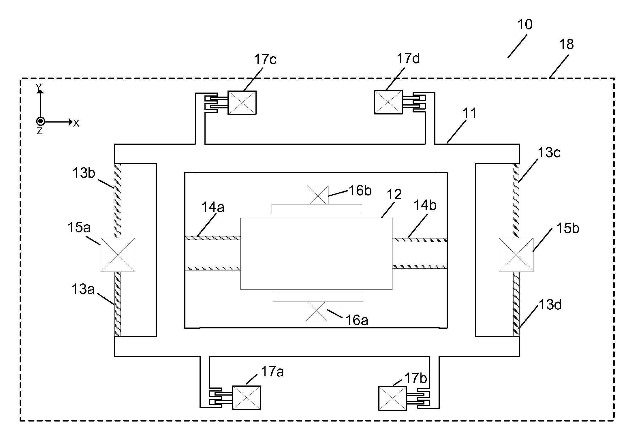
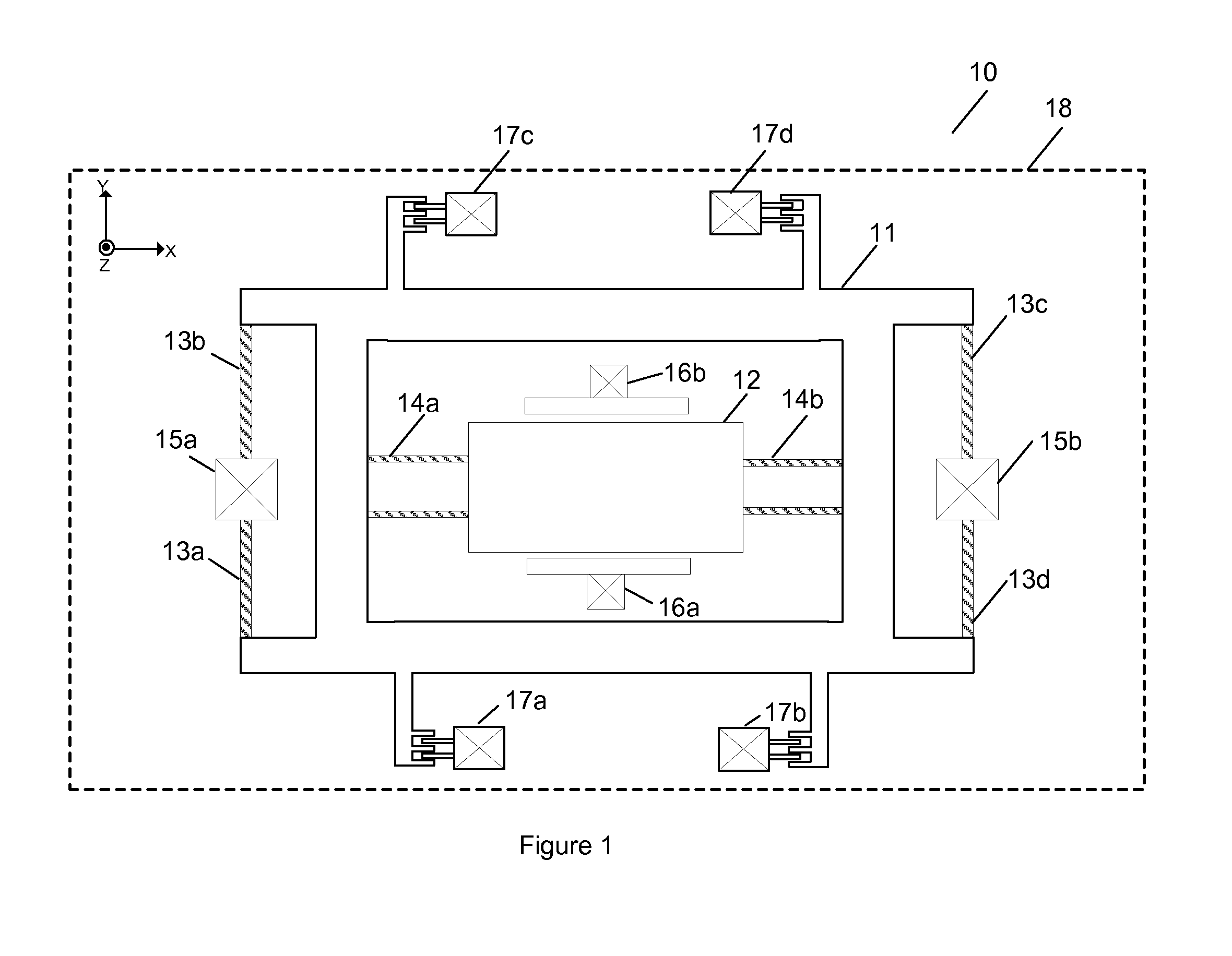
[0020]FIG. 1 illustrates an embodiment of a conventional micro machined yaw gyroscope 10. The yaw gyroscope 10 is comprised of a drive frame 11, a proof mass 12, drive springs 13a-13d, sense springs 14a and 14b, anchors 15a and 15b, transducers 16a and 16b, and electrostatic drive combs 17a-17d. The yaw gyroscope 10 is suspended over and para...


PUM


Abstract

A system and method in accordance with an embodiment reduces the cross-axis sensitivity of a gyroscope. This is achieved by building a gyroscope using a mechanical transducer that comprises a spring system that is less sensitive to fabrication imperfection and optimized to minimize the response to the rotations other than the intended input rotation axis. The longitudinal axes of the first and second flexible elements are parallel to each other and parallel to the first direction

Description

CROSS-REFERENCE TO RELATED APPLICATION[0001]Under 35 USC 119(e), this application claims priority to U.S. provisional application Ser. No. 61 / 553,031 filed on Oct. 28, 2011.FIELD OF THE INVENTION[0002]The present invention relates generally to MEMS devices and more particularly to springs utilized in such devices.BACKGROUND OF THE INVENTION[0003]A gyroscope is a sensor that measures angular velocity about a sensitive axis. An ideal yaw gyroscope is sensitive to angular velocity about the Z-axis, which is normal to a plane of the sensor. Ideal pitch and roll gyroscopes are sensitive to angular velocities about the X-axis and the Y-axis which are orthogonal in the plane of the sensor. Ideally, all three gyroscope sensitive axes are mutually orthogonal.[0004]Fabrication imperfections can cause the sensitive axis to deviate from the ideal input axis. For example a yaw gyroscope, which responds to angular velocity about the Z-axis, can also respond to angular velocity about the X-axis an...

Claims


Application Information

Patent Timeline
Patent Type & Authority Applications(United States)
IPC IPC(8): G01C19/56
CPCG01C19/5755G01C19/5733
Inventor SEEGER, JOSEPHANAC, OZAN
Owner INVENSENSE
Why Eureka
Try Eureka