
Microelectromechanical accelerometer device

a microelectromechanical and accelerometer technology, applied in the direction of measurement devices, speed/acceleration/shock measurement, instruments, etc., can solve the problems of increasing the cross-axis error of such accelerometer devices, and the combination of requirements of high-g and low-g accelerometers in a compact structure is very demanding, so as to reduce the cross-axis sensitivity

Active Publication Date: 2017-03-30
MURATA MFG CO LTD
View PDF4 Cites 9 Cited by
  • Summary
  • Abstract
  • Description
  • Claims
  • Application Information

AI Technical Summary

Benefits of technology

The patent is about a small device that can detect acceleration in two directions, but is less sensitive to movement in the direction between the two directions. This makes it easier to get accurate readings from the device.

Problems solved by technology

However, the spring structures tend to allow perpendicular acceleration to the sensed motion, and thereby increase cross axis error of such acceleration sensor devices.
Different types of acceleration sensors have different requirements, and a specific challenge is detection of acceleration in different ranges.
Combining requirements for high-g and low-g accelerometers in a compact structure is very demanding.

Method used


Image

  • Microelectromechanical accelerometer device
  • Microelectromechanical accelerometer device
  • Microelectromechanical accelerometer device

Examples


Embodiment Construction

[0023]The following embodiments are exemplary. Although the specification may refer to “an”, “one”, or “some” embodiment(s), this does not necessarily mean that each such reference is to the same embodiment(s), or that the feature only applies to a single embodiment. Single features of different embodiments may be combined to provide further embodiments.

[0024]In the following, features of the invention will be described with a simple example of a device architecture in which various embodiments of the invention may be implemented. Only elements relevant for illustrating the embodiments are described in detail. Various implementations of microelectromechanical devices that are generally known to a person skilled in the art may not be specifically described herein.

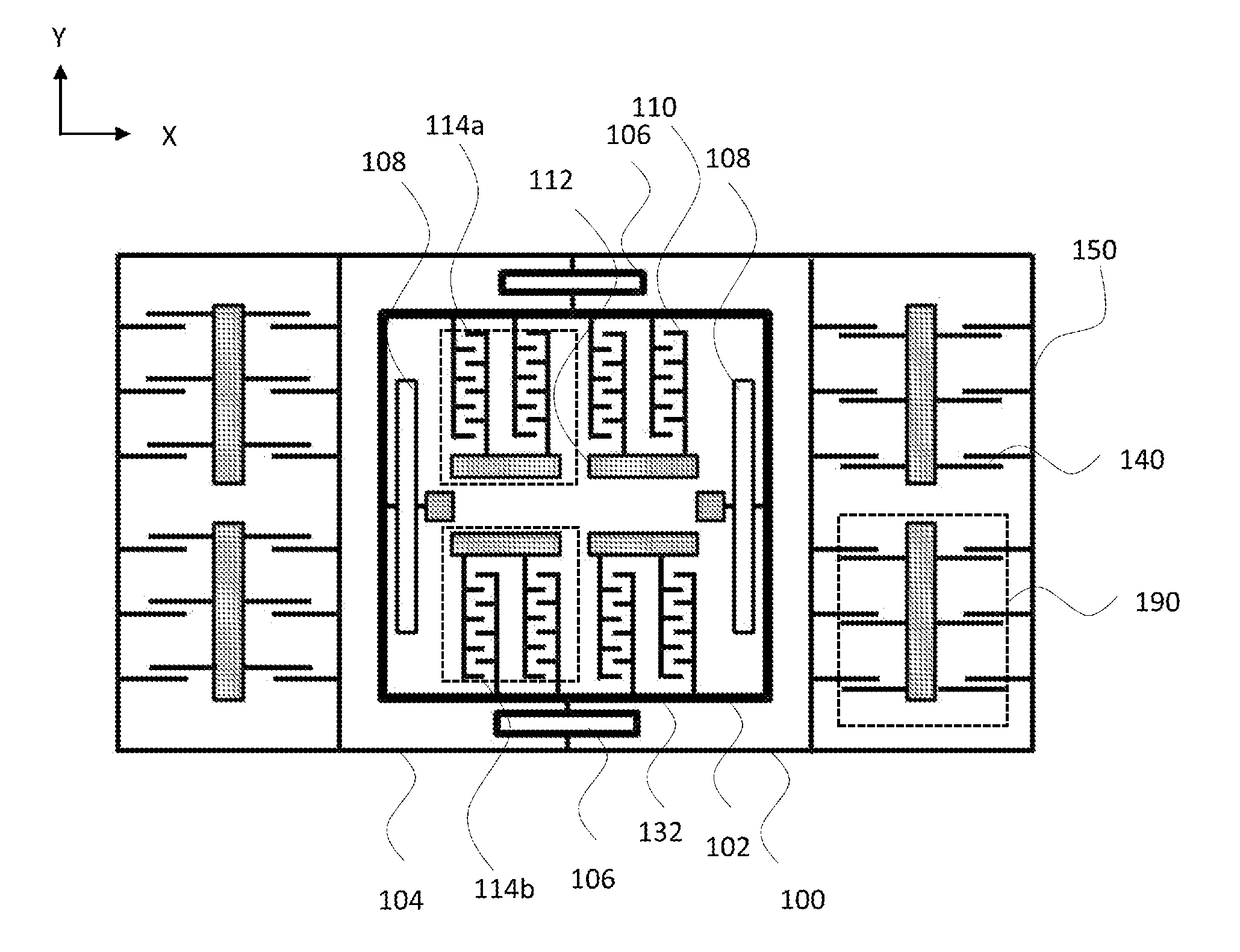
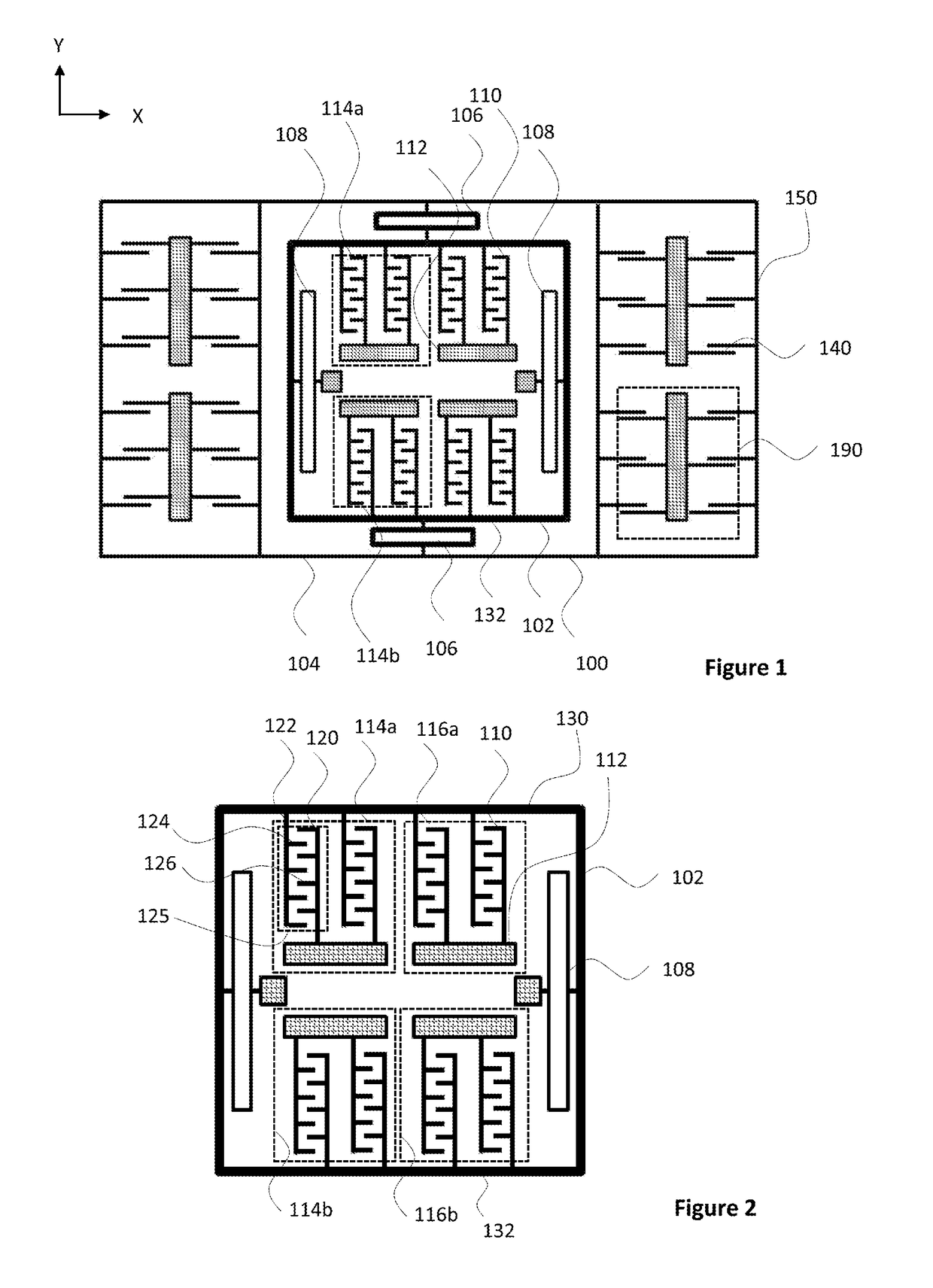
[0025]FIG. 1 illustrates basic elements of a microelectromechanical structure applicable in a microelectromechanical system (MEMS) accelerometer device. FIG. 1 shows a top view to a part of a planar structure layer forming t...


PUM


Abstract

The structure enables two-directional sensing of accelerations with compact component dimensions and with minimal cross-axis sensitivity. The rotation mass includes a first frame and a second frame. In one sense direction, the structure employs a combined proof mass of the first frame and the second frame, which improves the signal to noise level achievable with said device dimensions. In the other sense direction, a detection structure with at least two sensing elements is used to detect displacements of the proof mass of the second frame. Due to the specific internal configuration of the detection structure, signal contributions of the sensing elements in the one direction cancel each other.

Description

BACKGROUND[0001]The present invention relates to microelectromechanical systems and especially to a microelectromechanical structure for measuring accelerations and a microelectromechanical accelerometer device.DESCRIPTION OF THE RELATED ART[0002]Microelectromechanical structures can be applied to quickly and accurately detect changes in physical properties. An example of such detection is measurement of acceleration experienced by an object. Accelerometers can also be used as inclinometers to measure the component of earth's gravity in a measuring direction.[0003]The principle of acceleration sensing is simple and reliable: inertia of a moving body is converted into force according to Newton's second law. The basic elements of the accelerometer are the spring, the proof mass and the surrounding support structures. The spring connects the mass to the support. When the speed of the sensor changes, the proof mass is forced to follow the change via the spring coupling. A force is neede...

Claims


Application Information

Patent Timeline
Patent Type & Authority Applications(United States)
IPC IPC(8): G01P15/125
CPCG01P2015/0811G01P15/125G01P15/18G01P2015/0848
Inventor LIUKKU, MATTINISKANEN, SEVERI
Owner MURATA MFG CO LTD
Learn More