
2D-to-3D DELAY COMPENSATION SYSTEM AND METHOD THEREOF

Inactive Publication Date: 2012-05-24
HIMAX MEDIA SOLUTIONS
View PDF1 Cites 11 Cited by
  • Summary
  • Abstract
  • Description
  • Claims
  • Application Information

AI Technical Summary

Benefits of technology

[0009]In view of the foregoing, it is an object of the embodiment of the present invention to provide a 2D-to-3D delay compensation system and method thereof to compensate the video processing delay caused by the display device to perform image processing for the right and left images.

Problems solved by technology

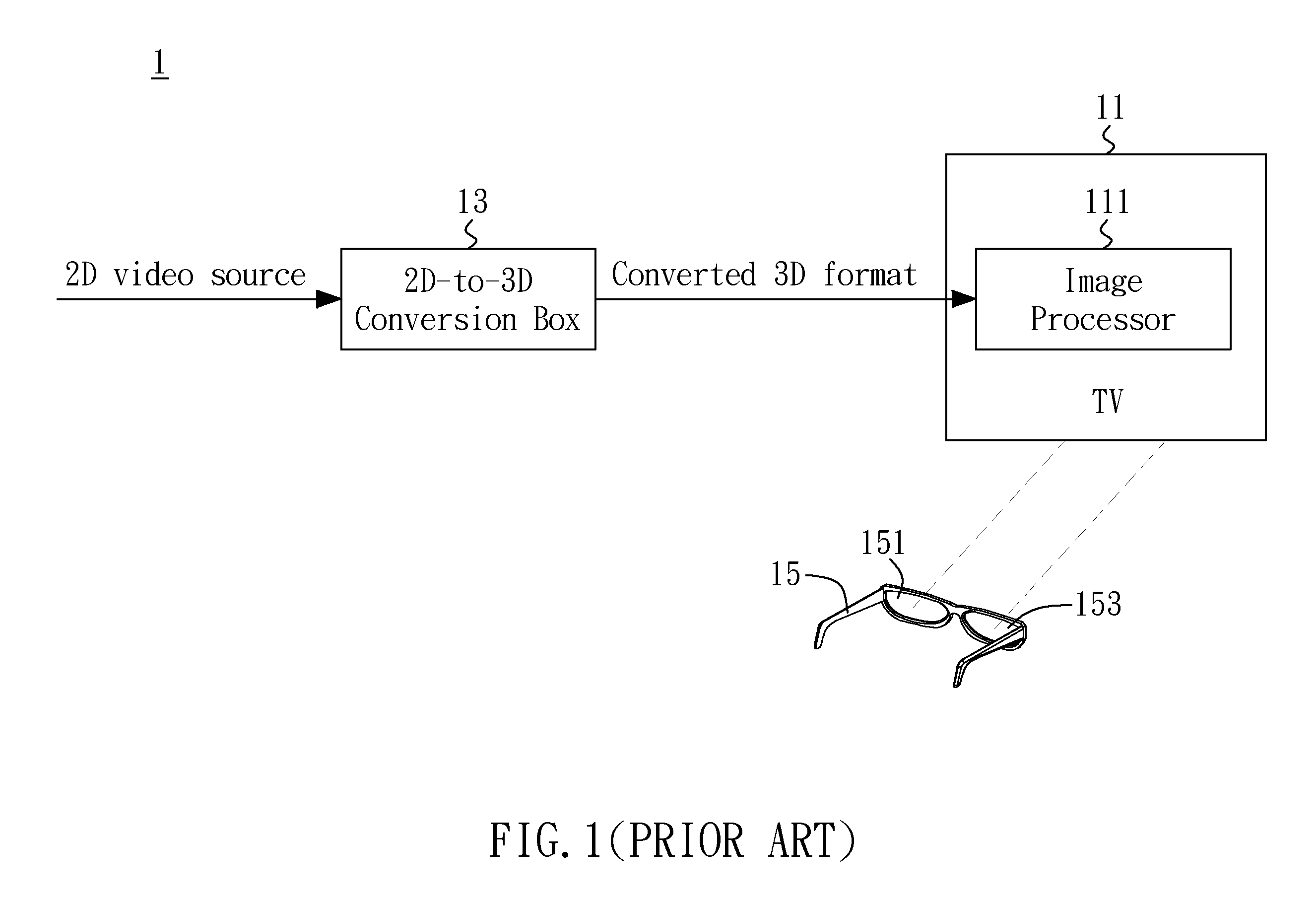
It will introduce a finite delay which is usually caused by the video processing delay of the display device 11.
As a result, the viewer's 3D impression will be adversely impacted.

Method used


Image

  • 2D-to-3D DELAY COMPENSATION SYSTEM AND METHOD THEREOF
  • 2D-to-3D DELAY COMPENSATION SYSTEM AND METHOD THEREOF
  • 2D-to-3D DELAY COMPENSATION SYSTEM AND METHOD THEREOF

Examples


Embodiment Construction

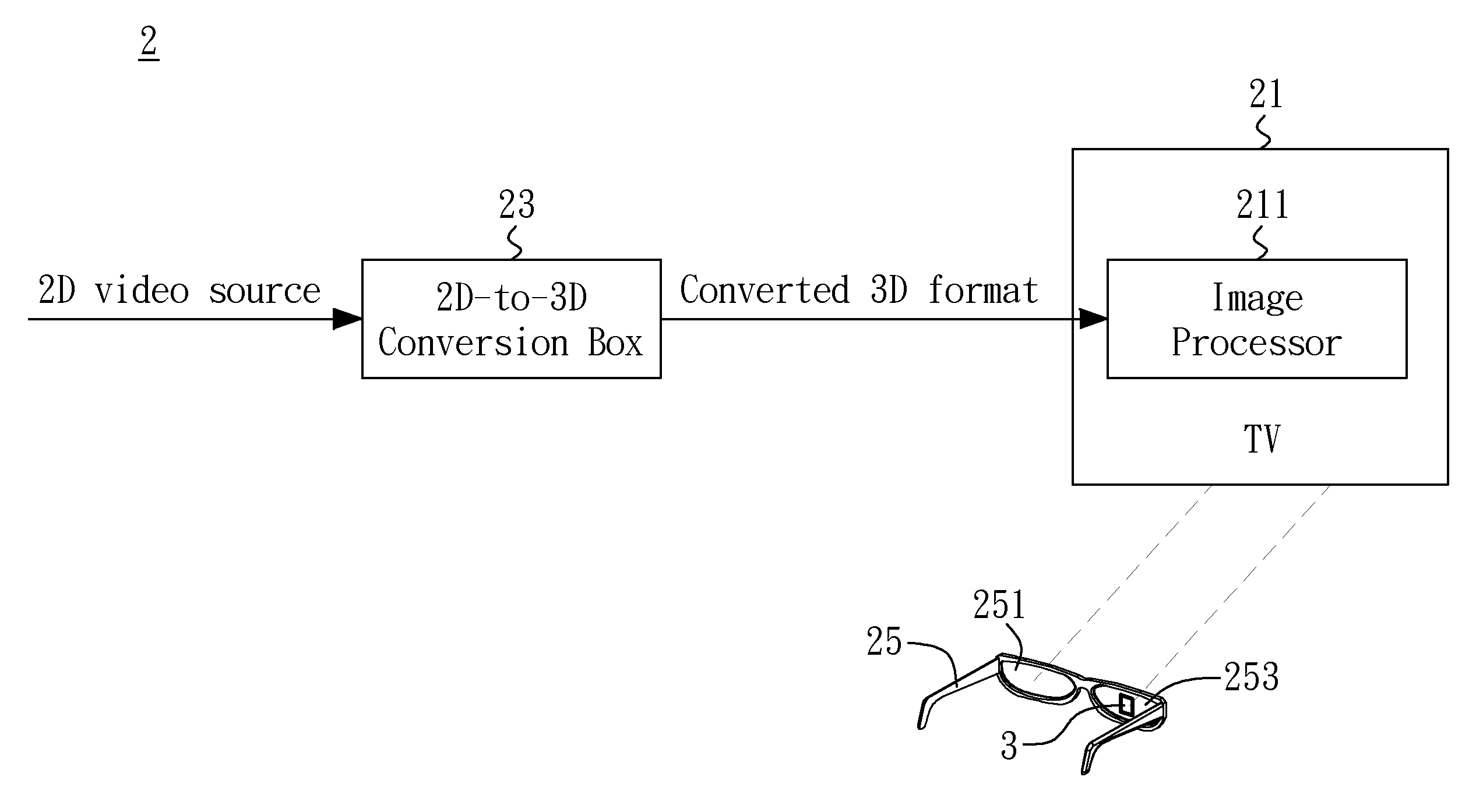
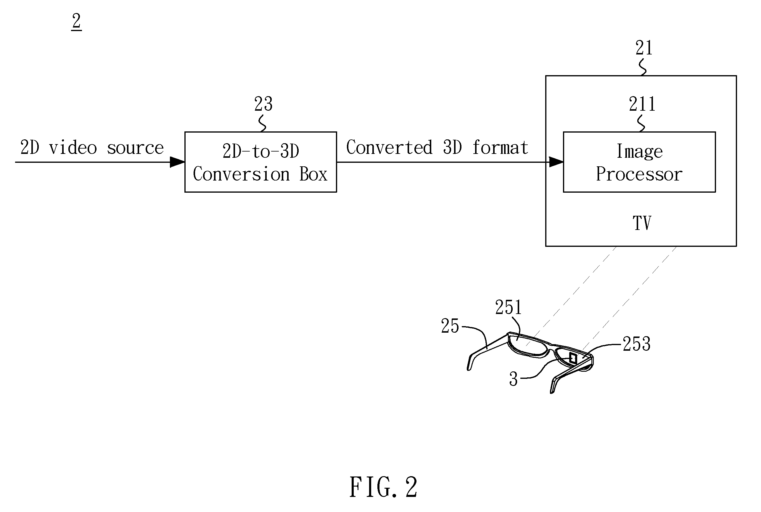
[0016]FIG. 2 is a block diagram illustrating a 2D-to-3D delay compensation system according to one embodiment of the present invention. The 2D-to-3D delay compensation system 2, as shown in FIG. 2, comprising a 2D-to-3D conversion box 23 and a pair of 2D-to-3D shutter glasses 25, is tied in with a display device 21. The 2D-to-3D conversion box 23 is connected with the display device 21, and is configured to convert an input 2D video source to a converted 3D output format. The converted 3D output format frame then may be transmitted to the display device 21 to display. Specifically, the 2D video source includes a series of frames. It may be implemented by the Depth-Image-Based Rendering (DIBR) technique in the 2D-to-3D conversion box 23 to calculate the binocular disparity of each frame of the original 2D video source, and further generate (or synthesize) a left (L) image and a right (R) image to be displayed by the display device 21 in sequence.

[0017]The pair of shutter glasses 25 c...


PUM


Abstract

A 2D-to-3D delay compensation method for making a pair of shutter glasses be synchronization with a display device's playback of a video source is disclosed. The display device is coupled with a 2D-to-3D conversion box. The method includes the following steps: firstly, the 2D-to-3D conversion box sends out a calibration pattern to the display device. Then, a shutter control signal is sent out after waiting a delay time to switch on and off the left and right lenses of the pair of shutter glasses. Subsequently, the calibration pattern is detected. Finally, determine whether the delay time must be adjusted or not according to the detecting result.

Description

BACKGROUND OF THE INVENTION[0001]1. Field of the Invention[0002]The present invention generally relates to delay compensation system, and more particularly to a 2D-to-3D delay compensation system and method thereof.[0003]2. Description of Related Art[0004]Formerly the video displayed in a panel display device such as liquid crystal display (LCD) TV is two-dimensional (2D) image source. In the wake of developments in displaying technology, the applications of displaying three-dimensional (3D) visual effect have increased with each passing day, such as 3D films, 3D games, and product displaying, etc. It results that the 3D imaging system becomes more practical and popular.[0005]Besides using 3D display to achieve 3D imaging effect, the displays with general functions can be connected with a 2-to-3D conversion box to generate 3D visual effect as well. Please refer to FIG. 1, which shows a block diagram of a conventional 2D-to-3D imaging system 1. The 2D-to-3D imaging system 1, which co...

Claims


Application Information

Patent Timeline
IPC IPC(8): H04N13/04
CPCH04N13/026H04N2213/008H04N13/0497H04N13/0438H04N13/341H04N13/261H04N13/398
Inventor CHENG, SHIN-SHIUANLIU, SHU-MINGLEE, HUNG-CHIA
Owner HIMAX MEDIA SOLUTIONS
Learn More