
Inlet particle separator system

a technology of particle separator and separator plate, which is applied in the direction of separation process, efficient propulsion technology, machines/engines, etc., can solve the problems of substantial damage, vtol-type aircraft engines such as helicopter gas turbine engines are susceptible to damage, and aircraft engines such as vertical takeoff and landing (vtol-type) aircraft engines are vulnerable to damag

Inactive Publication Date: 2012-05-31
GENERAL ELECTRIC CO
View PDF14 Cites 20 Cited by
  • Summary
  • Abstract
  • Description
  • Claims
  • Application Information

AI Technical Summary

Benefits of technology

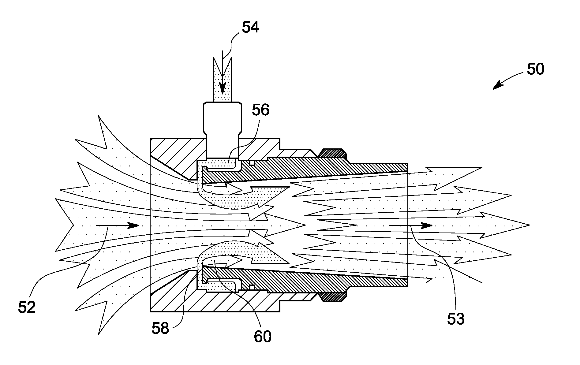
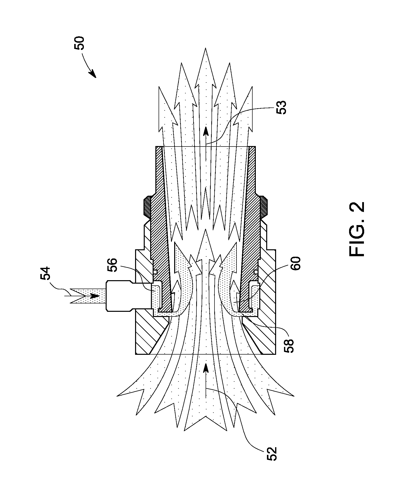
[0006]In accordance with another embodiment of the invention, a fluidic device is provided. The fluidic device includes an inlet and a chamber for receiving a flow of compressed air from a compressor of a gas turbine engine. The fluidic device also includes a nozzle for providing a jet of compressed ai

Problems solved by technology

Generally, aircraft engines are susceptible to damage from foreign particulate matter introduced into air inlets of such engines.
Mostly, vertical takeoff and landing (VTOL) aircraft engines such as helicopter gas turbine engines are vulnerable to damage due to smaller particulate matter like sand or ice.
These VTOL aircrafts operate at various conditions where substantial quantities of sand or ice may become entrained in intake air supplied to the gas turbine engine and can cause substantial damage.
For example, a helicopter engine operating at low altitudes over a desert looses performance rapidly due to erosion of the engine blades due to ingestion of sand and dust particles.
However, such IPS system having the blower system has severe performance disadvantages due to constant operation during flight even in absence of particulate matter at higher alltitudes.
Due to constant running of IPS blower, there is large consumption of power during flight at high altitudes.
Also, the IPS system with a blower increases the overall cost in addition to weight of the IPS system, thereby, affecting the performance of the gas turbine engine.
Furthermore, the life of the blower system is limited and requires frequent maintenance and potentially less expensive while delivering identical or better performance.

Method used


Image

  • Inlet particle separator system
  • Inlet particle separator system
  • Inlet particle separator system

Examples


Embodiment Construction

[0012]When introducing elements of various embodiments of the present invention, the articles “a,”“an,”“the,” and “said” are intended to mean that there are one or more of the elements. The terms “comprising,”“including,” and “having” are intended to be inclusive and mean that there may be additional elements other than the listed elements. Any examples of operating parameters are not exclusive of other parameters of the disclosed embodiments.

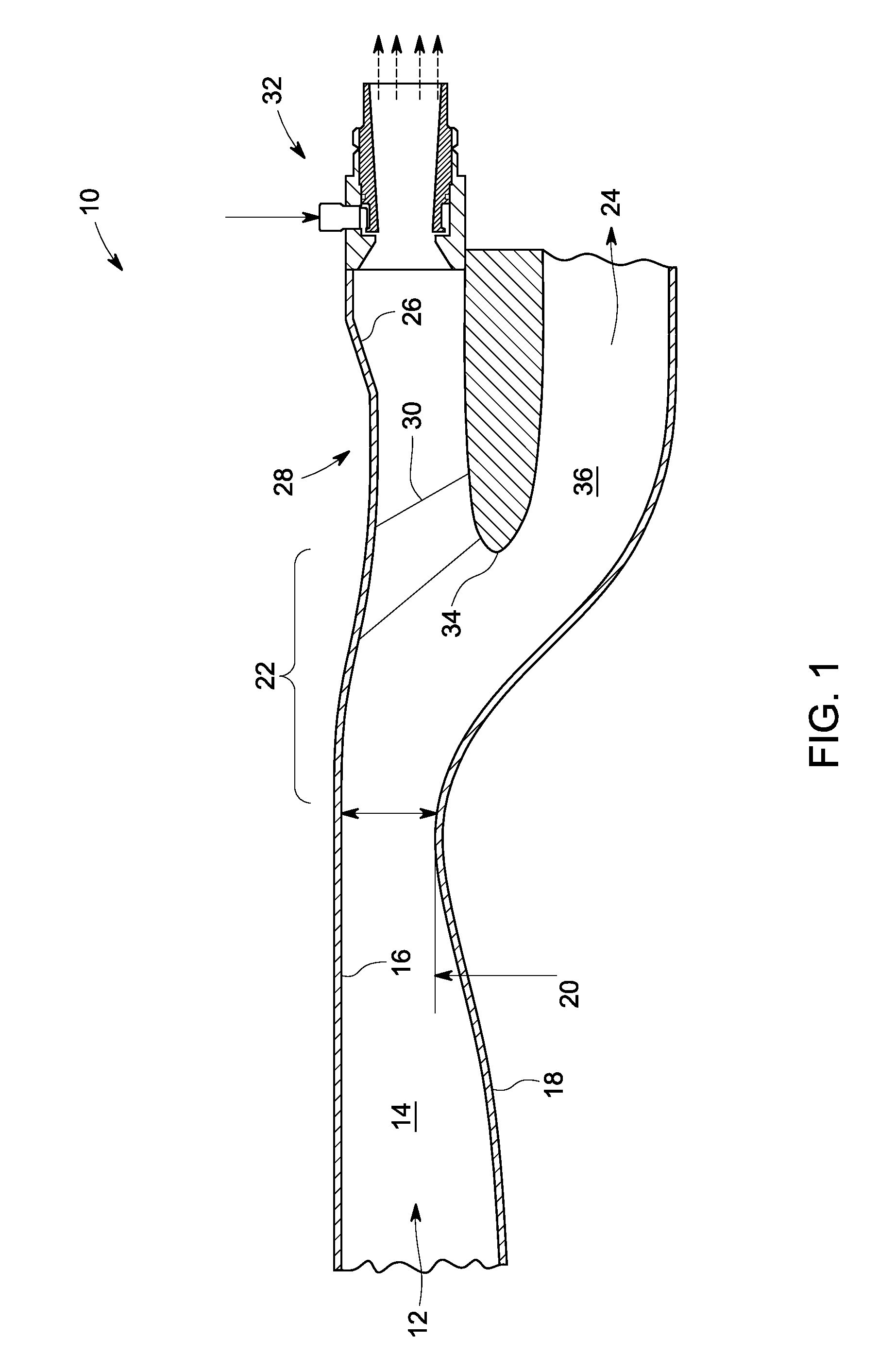
[0013]FIG. 1 shows an inlet particle separator system 10 in accordance with an embodiment of the present invention. The inlet particle separator system 10 is a unit that is designed to be mounted on the front end of an aircraft engine (not shown). In one embodiment, the inlet particle separator system 10 is a complete detachable unit. The function of the inlet particle separator 10 is to separate extraneous matter from engine inlet air and direct the resulting substantially cleaned air into the engine's core. As shown, outside air is drawn into...


PUM

PropertyMeasurementUnit
Flow rateaaaaaaaaaa

Abstract

An inlet particle separator system is provided. The system includes an axial flow separator for separating air from an engine inlet into a first flow of substantially contaminated air and a second flow of substantially clean air. The system also includes a scavenge subsystem in flow communication with the axial flow separator for receiving the first flow of substantially contaminated air. Finally, the system includes a fluidic device disposed in flow communication with the first flow of substantially contaminated air for inducting air through the scavenge subsystem and the engine inlet.

Description

BACKGROUND[0001]The invention relates generally to an inlet particle separator system and more particularly to a system and method of operating the inlet particle separator system having a fluidic device.[0002]Generally, aircraft engines are susceptible to damage from foreign particulate matter introduced into air inlets of such engines. Mostly, vertical takeoff and landing (VTOL) aircraft engines such as helicopter gas turbine engines are vulnerable to damage due to smaller particulate matter like sand or ice. These VTOL aircrafts operate at various conditions where substantial quantities of sand or ice may become entrained in intake air supplied to the gas turbine engine and can cause substantial damage. For example, a helicopter engine operating at low altitudes over a desert looses performance rapidly due to erosion of the engine blades due to ingestion of sand and dust particles. In order to solve this problem, various inlet particle separator (IPS) systems have been developed ...

Claims


Application Information

Patent Timeline
IPC IPC(8): F02C7/052
CPCB01D45/06B64D33/02Y02T50/675F05D2260/607B64D2033/0246Y02T50/60
Inventor KENYON, ROSS HARTLEYJOSHI, NARENDRA DIGAMBEREVULET, ANDREI TRISTAN
Owner GENERAL ELECTRIC CO
Learn More