

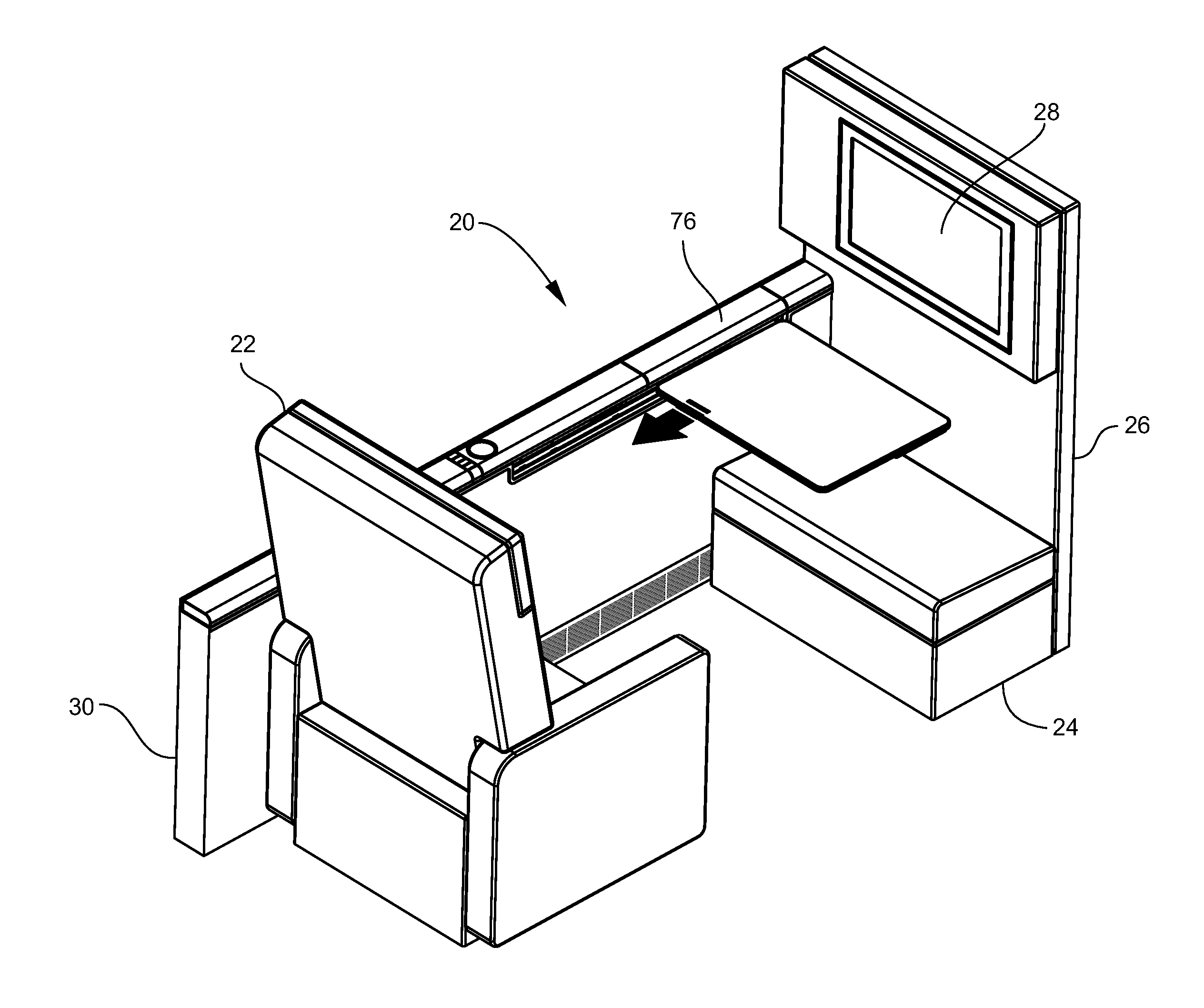
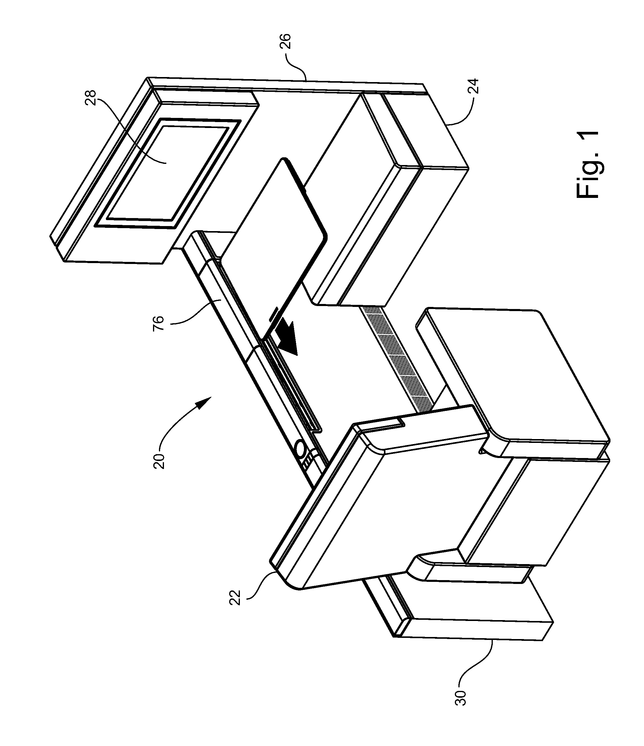
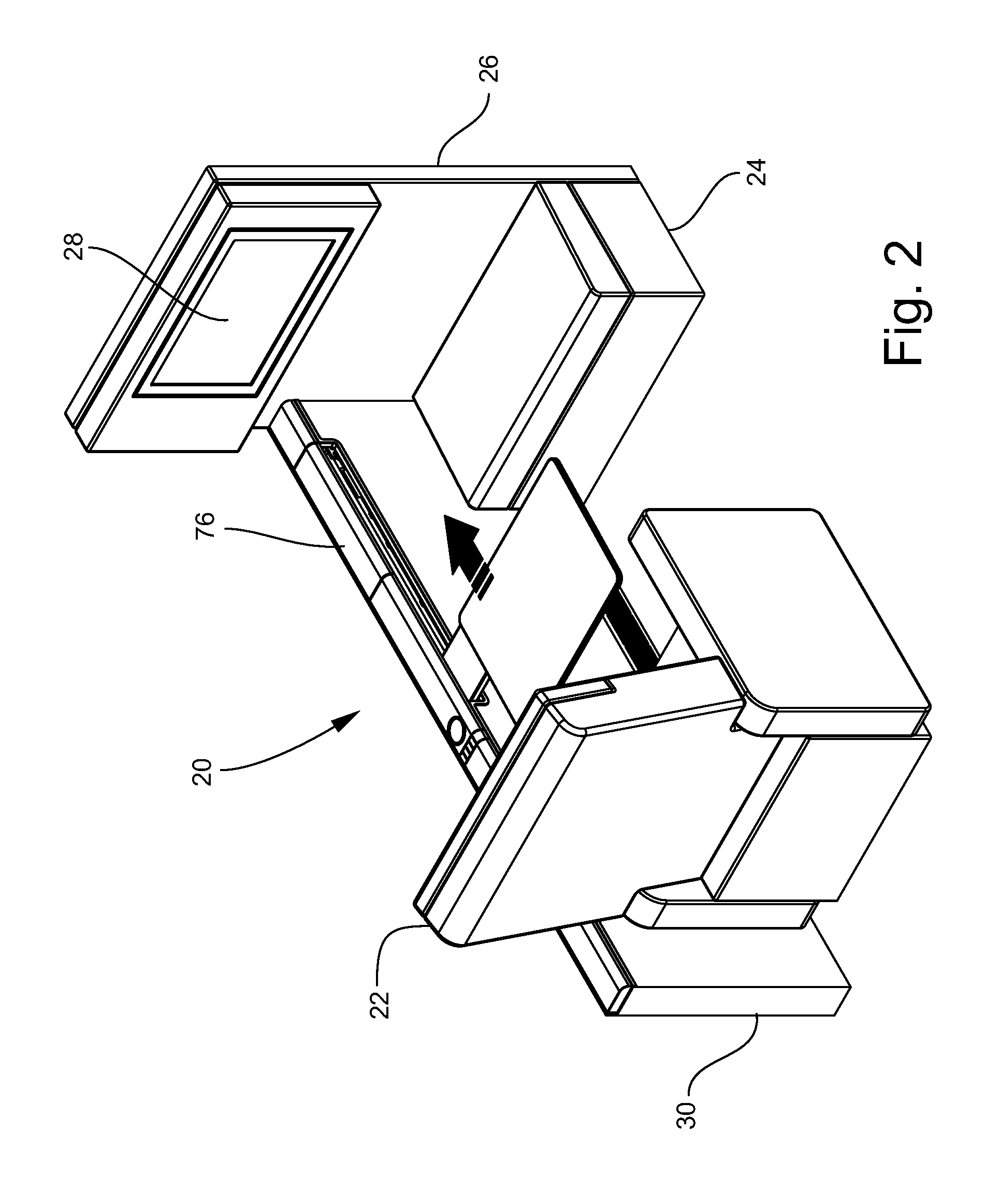
Stowable passenger seat tray table
a passenger seat and tray table technology, applied in the direction of seat arrangement, aircraft crew accommodation, transportation and packaging, etc., can solve the problem of not providing a supporting arm assembly configured to translate the table top in fore and aft directions
- Summary
- Abstract
- Description
- Claims
- Application Information
AI Technical Summary
Benefits of technology
Problems solved by technology
Method used
Image

Examples
Embodiment Construction
[0040]The present invention will now be described more fully hereinafter with reference to the accompanying drawings in which exemplary embodiments of the invention are shown. However, the invention may be embodied in many different forms and should not be construed as limited to the representative embodiments set forth herein. The exemplary embodiments are provided so that this disclosure will be both thorough and complete, and will fully convey the scope of the invention and enable one of ordinary skill in the art to make, use and practice the invention.
[0041]As used herein, the terms ‘horizontal’ and ‘vertical’ used in conjunction with the positions and orientations of the tray table, guide rails and other components of the tray table assembly are defined with reference to the floor of the passenger seating surface of the aircraft, which is envisioned to change with respect to gravitational horizontal during flight. As used herein, the terms ‘fore’ and ‘aft’ used in conjunction w...
PUM
 Abstract
Description
Claims
Application Information