Method and system for laying a submarine pipeline

Active Publication Date: 2020-04-09
SAIPEM SPA
View PDF0 Cites 1 Cited by
  • Summary
  • Abstract
  • Description
  • Claims
  • Application Information

AI Technical Summary

Benefits of technology

[0010]A particular object of the invention is to avoid the risk of damage to the pipeline and to the pipeline end termination devic

Problems solved by technology

The disadvantage of this system consists in the uncertainty of the final positioning of the pipeline end termination device with respect to the target position.
A further disadvantage consists in the need for a completely free space of about 60-100 m between the anchor and the target position of the pipeline end termination device.
This condition may be not feasible due to the presence of well heads and of other structures and sy

Method used


Image

  • Method and system for laying a submarine pipeline
  • Method and system for laying a submarine pipeline
  • Method and system for laying a submarine pipeline

Examples


Example

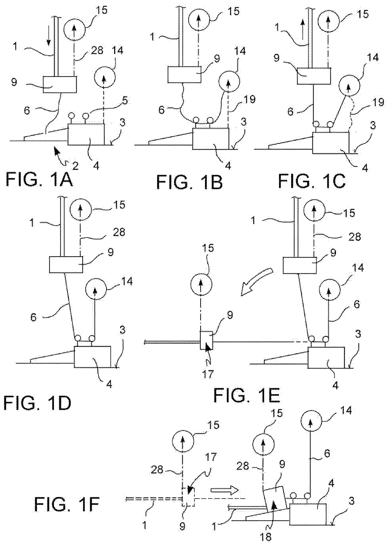
[0068]With reference to the figures, a laying method of an off-short pipeline 1 comprises:

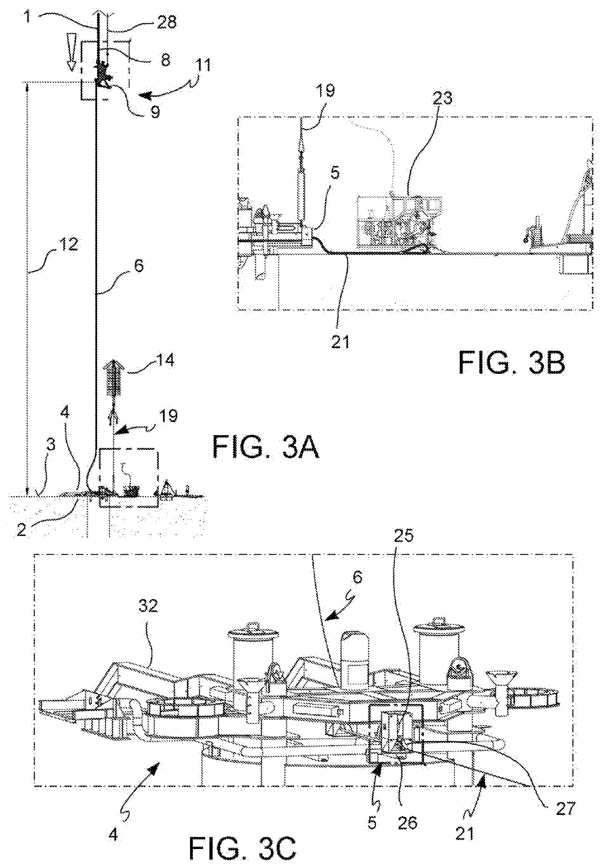
[0069]installing a fixed receiving structure 4 having a redirecting device 5 for a damping cable 6 in a target position 2 on the seabed 3,

[0070]on a laying vessel 7, providing the pipeline 1 with an initial end length 8 to which a pipeline end termination device 9 is mounted,

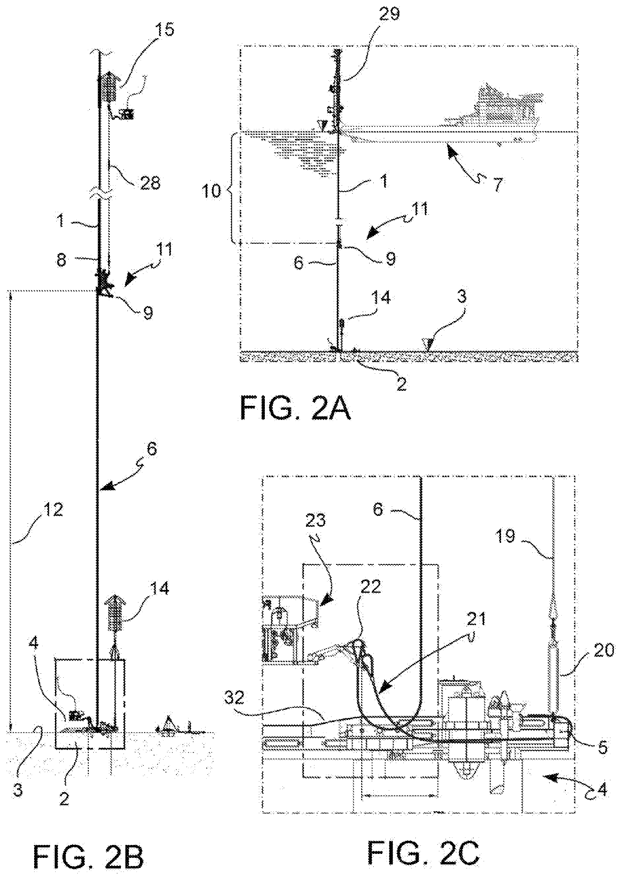
[0071]connecting an underwater suspension buoy 15 to the pipeline end termination device 9, the underwater suspension buoy 15 applying a suspension force which is directed vertically upwards to the pipeline end termination device 9 (FIGS. 1D, 2B, 5A),

[0072]paying-out a first length (i.e. a first stretch) 10 of the pipeline 1 with the pipeline end termination device 9 from the laying vessel 7 vertically towards the seabed 3 to a provisional anchoring position 11, in which the initial end length 8 has an approximately vertical orientation with a vertical safety distance 12 between the pipeline end termination device 9 and the...


PUM


Abstract

A method of laying an off-shore pipeline (1) comprises: —installing on the seabed (3) a fixed receiving structure (4) having a redirecting device (5), —paying-out from a laying vessel (7) a pipeline (1) with the pipeline end termination device (9) vertically towards the seabed (3), —extending a damping cable (6) from the pipeline end termination device (9) through the redirecting device (5) to an underwater damping buoy (14), —connecting an underwater suspension buoy (15) to the pipeline end termination device (9), —inclining the pipeline (1) from a vertical orientation towards the horizontal orientation, using: —the suspension buoy (14) to counterbalance at least part of the weight of the pipeline end termination device (9), —the damping buoy (14) for damping the pipeline (1).

Description

[0001]The invention relates to a method and a system for laying a submarine pipeline, in particular for a step of initiating the laying of the pipeline.FIELD OF THE ART[0002]In a typical petroleum or natural gas off-shore pipeline laying scenario in deep and ultra-deep waters from hundreds to thousands of meters deep, e.g. 300 m-4000 m, both in the case of pipelines with continuous horizontal extension and in the case of pipelines with catenary extension or extending from the bottom upwards (risers), in an initial step a pipeline string is payed-out from a laying vessel, e.g. by means of a “J” laying tower which pays-out a pipeline string, provided aboard the laying vessel downwards, either vertically or nearly vertically. A pipeline end termination device (PLET), intended to be installed on the seabed and configured for connecting the pipeline to an application, e.g. a well head or a flow collector, is mounted at the free end of the pipeline string.[0003]One of the critical steps o...

Claims


Application Information

Patent Timeline
IPC IPC(8): F16L1/19B63B35/03
CPCF16L1/235F16L1/26E21B43/0107F16L1/19B23K2101/10B63B35/03F16L1/16F16L1/165F16L1/201
Inventor CONTI, FLAVIOFORESTALI, DIEGO
Owner SAIPEM SPA
Why Eureka
Try Eureka