
In-line motorized double break disconnect switch

a double-break, disconnect switch technology, applied in air-break switches, high-tension/heavy-dress switches, electrical equipment, etc., can solve the problems of reducing the service life of the switch. , to achieve the effect of obvious cost savings and advantageous commercial valu

Active Publication Date: 2020-01-02
CLEAVELANDPRICE ENTERPRISES
View PDF0 Cites 2 Cited by
  • Summary
  • Abstract
  • Description
  • Claims
  • Application Information

AI Technical Summary

Benefits of technology

This patent is about a new type of switch that can handle high voltages of electricity. The switch has a motor that drives it, and it is mounted on the upper tie plate of a switch. This design allows for counterbalancing of the switch blade, which makes it easier to open and close. The switch is also designed to work with three-phase electricity, and can communicate with each other and with a control room using radios. By eliminating the need for a separate mounting structure, the switch is more cost-effective and easier to install. Additionally, the patent explains how the switch can be powered by solar panels or a local AC source, making it more versatile and adaptable to different situations.

Problems solved by technology

The motor is mounted in the middle of and attached to the horizontally rotating switch blade, thereby the weight of the long switch blade is counterbalanced.
The weight of the switch blade is thereby counterbalanced with half of the weight on each side of the motor output shaft.
This division of weight of the switch blade by the central placement of the connection of the motor output shaft creates a left section of the switch blade that extends on one side of the transmission line when opening by rotating horizontally while simultaneously a right section of the switch blade extends on the opposite side of the transmission line thereby resulting in counterbalancing of the switch blade and elimination of the described prior art “rolling of the switch”.

Method used


Image

  • In-line motorized double break disconnect switch
  • In-line motorized double break disconnect switch
  • In-line motorized double break disconnect switch

Examples


Embodiment Construction

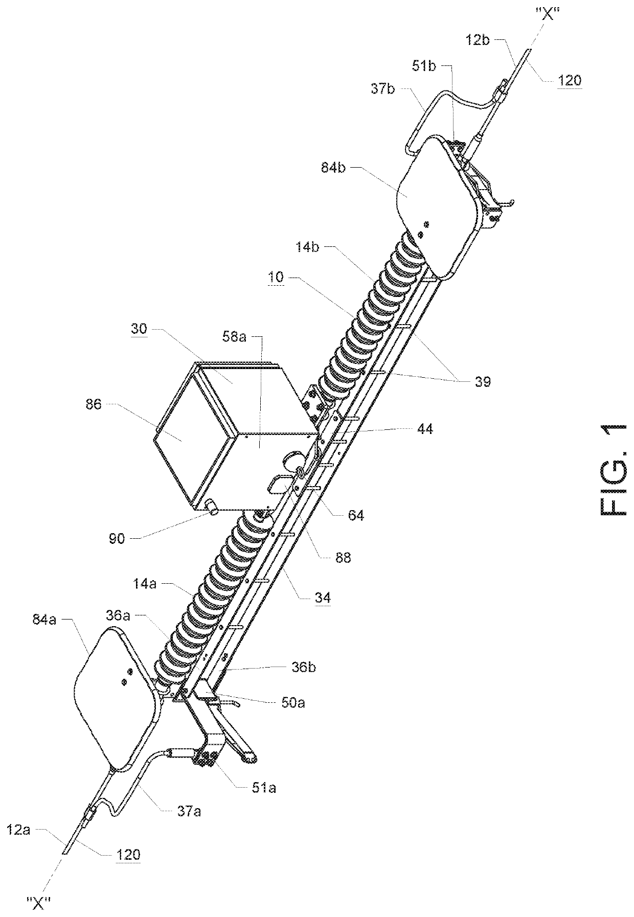
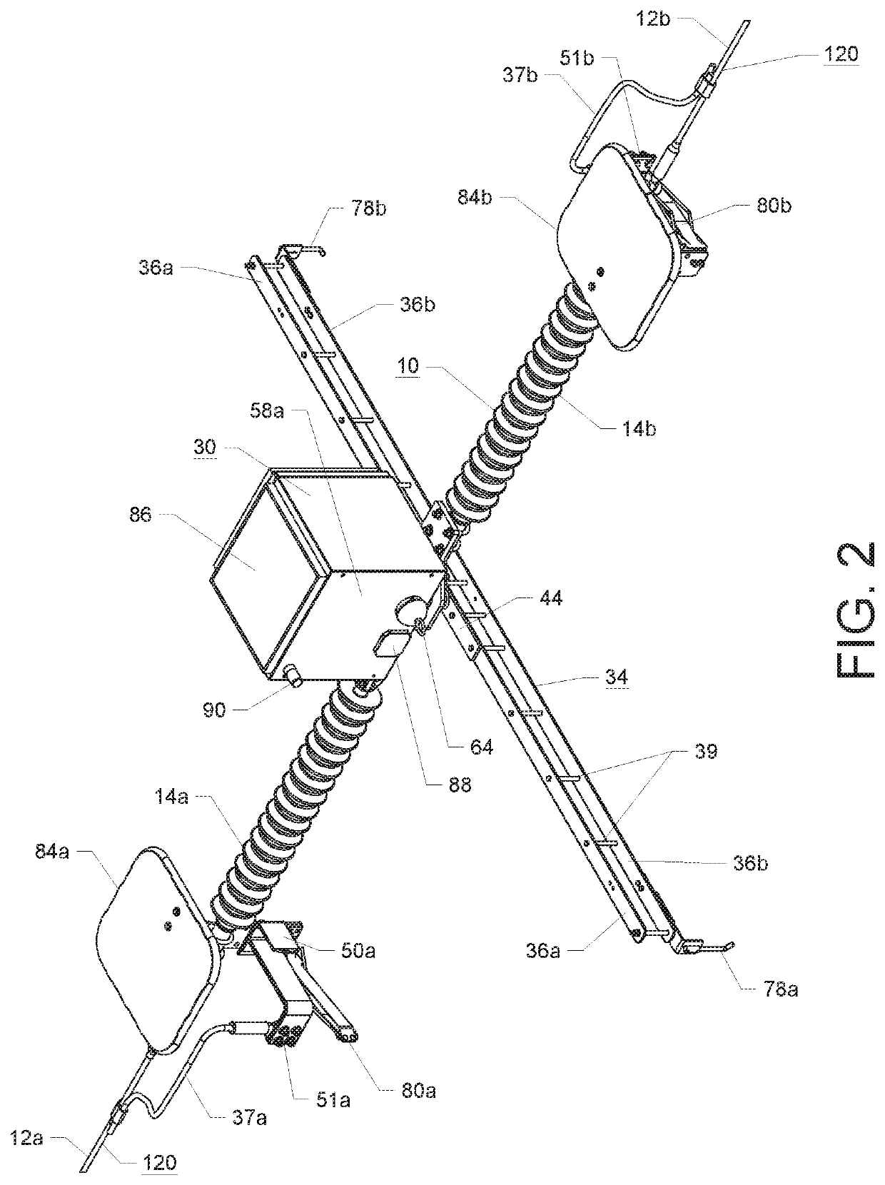
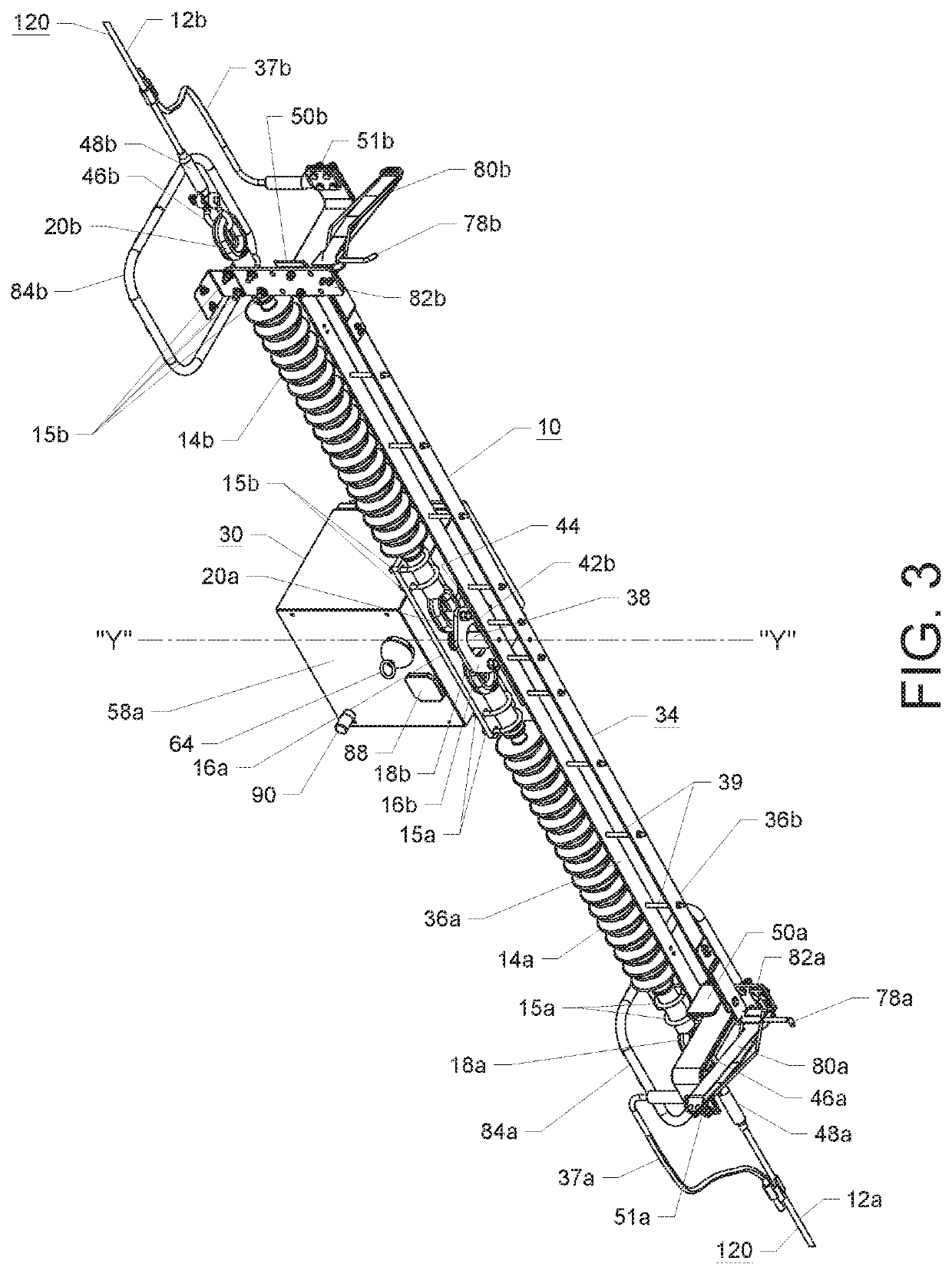
[0034]With reference to FIGS. 1-4, there is shown a radio controlled motorized in-line high voltage double break disconnect switch 10 of the present invention operatively suspended by and between cable conductors 12a, 12b of the transmission line conductor 120. With reference to FIG. 1, the in-line double break disconnect switch 10 of the present invention includes a pair of ganged elongated coaxially aligned polymer strain insulators 14a, 14b. As can be seen in FIG. 4, the first polymer insulator 14a has mounted at its respective first end 25a and second end 25b first chain eye fittings 18a, 18b. The second polymer insulator 14b has mounted at its respective first end 27a and second end 27b second chain eye fittings 20a, 20b. The chain eye fittings 18a, 20a are attached respectively by clevises 46a, 46b and dead-end fittings 48a, 48b for respectively mounting each cut end of the transmission line 120, i.e., cable conductor 12a, 12b to the respective polymer insulator 14a, 14b which...


PUM


Abstract

A high voltage motor operated in-line double break disconnect switch suspended by an electric power line conductor wherein the switch includes a horizontally rotating switch blade, that is suspended by a motor output shaft attached to the midpoint of a blade of the switch blade to balance the blade. A communication system for controlling the motor including a switch mounted radio which may be controlled by another radio located at a distance and powered by a solar charged battery or alternatively controlled by a hand-held controller. The motorized in-line double break disconnect switch may also be arranged in a three phase installation in a two-way or three-way switching arrangement attached to a utility pole or other structure. The communication system controlled motorized in line double break disconnect switch may in addition be arranged in a phase over phase switching arrangement supported by a utility pole or other structure.

Description

CROSS-REFERENCE TO RELATED APPLICATION[0001]This is application claims the benefit of U.S. Provisional Application No. 62 / 692,932 filed Jul. 2, 2018, which is incorporated herein by reference in its entirety.BACKGROUND OF THE INVENTION[0002]The present invention relates generally to an air break disconnect switch for high voltage electrical applications and, more particularly, to an in-line high voltage air break disconnect switch that mounts in-line with the transmission line conductor without the need of a group operated switch with associated ground supported mounting structure. Such an in-line high voltage disconnect switch hangs from and is supported by its associated transmission line.[0003]One example of such an in-line high voltage disconnect switch is a vertical break disconnect switch currently manufactured and sold by Cleaveland / Price Inc., of Trafford, Pa., the present Assignee, as a type ILO-C, Hookstick Operated In-Line Transmission Switch. The switch is described in C...

Claims


Application Information

Patent Timeline
Patent Type & Authority Applications(United States)
IPC IPC(8): H01H33/28H01H33/666H01H33/02H01H33/12H01H33/20H01H33/65H01H33/42H01H33/14
CPCH01H33/42H01H33/126H01H33/62H01H33/14H01H33/20H01H33/022H01H33/28H01H33/6661H01H33/65
Inventor KOWALIK, PETER M.SHYCHUCK, JAMES R.
Owner CLEAVELANDPRICE ENTERPRISES
Learn More