Multicarrier based optical signal transmitting apparatus and optical signal receiving apparatus

a multi-carrier, optical signal technology, applied in the direction of electromagnetic transmission, multi-channel communication, wavelength-division multiplex system, etc., can solve the problem that the signal cannot be accommodated in the fixed frequency interval defined by itu-t standards, 400 gb/s cannot be accommodated in the existing fixed frequency grid, etc., to achieve the effect of lessening the requirements of the optical signal to noise ratio

Inactive Publication Date: 2015-03-31
ELECTRONICS & TELECOMM RES INST
View PDF8 Cites 2 Cited by
  • Summary
  • Abstract
  • Description
  • Claims
  • Application Information

AI Technical Summary

Benefits of technology

[0006]The present invention has been made in an effort to provide an optical signal transmitting apparatus and an optical signal receiving apparatus where a high-speed optical signal can be accommodated in both a fixed frequency grid mode and a flexible frequency grid mode, and a long-distance transmission of a high-speed signal can be achieved by lessening the requirements of an optical signal to noise ratio.
[0020]According to the present invention, a high-speed optical signal can be accommodated in both a fixed frequency grid mode and a flexible frequency grid mode, and a long-distance transmission of a high-speed signal can be achieved by lessening the requirements of an optical signal to noise ratio.

Problems solved by technology

A non-return-to-zero (NRZ) method where only existing magnitudes are turned on and off through a modulation method of generating high-speed signals and transmitting the high-speed signals through optical links has a limit due to a limit in bandwidths of devices and high optical signal-to-noise ratio (OSNR) requirements.
However, if a transmission speed per one channel of an optical signal reaches 400 Gb / s, exceeding 100 Gb / s, the signal cannot be accommodated in the fixed frequency interval defined by ITU-T Standards.
It is because a bandwidth occupied by a signal becomes larger than 50 GHz due to a high transmission speed and thus an interference with a neighboring channel may occur.
Although a flexible frequency grid for freely changing a center frequency and a bandwidth of an optical signal is required to accommodate a 400 Gb / s optical signal together with an existing 40 Gb / s or 100 Gb / s optical signal in an optical transmission network, a 400 Gb / s cannot be accommodated in an existing fixed frequency grid.

Method used


Image

  • Multicarrier based optical signal transmitting apparatus and optical signal receiving apparatus
  • Multicarrier based optical signal transmitting apparatus and optical signal receiving apparatus
  • Multicarrier based optical signal transmitting apparatus and optical signal receiving apparatus

Examples


Embodiment Construction

[0037]Hereinafter, exemplary embodiments of the present invention will be described in detail with reference to the accompanying drawings. First of all, we should note that in giving reference numerals to elements of each drawing, like reference numerals refer to like elements even though like elements are shown in different drawings. In describing the present invention, well-known functions or constructions will not be described in detail since they may unnecessarily obscure the understanding of the present invention. It should be understood that although exemplary embodiment of the present invention are described hereafter, the spirit of the present invention is not limited thereto and may be changed and modified in various ways by those skilled in the art.

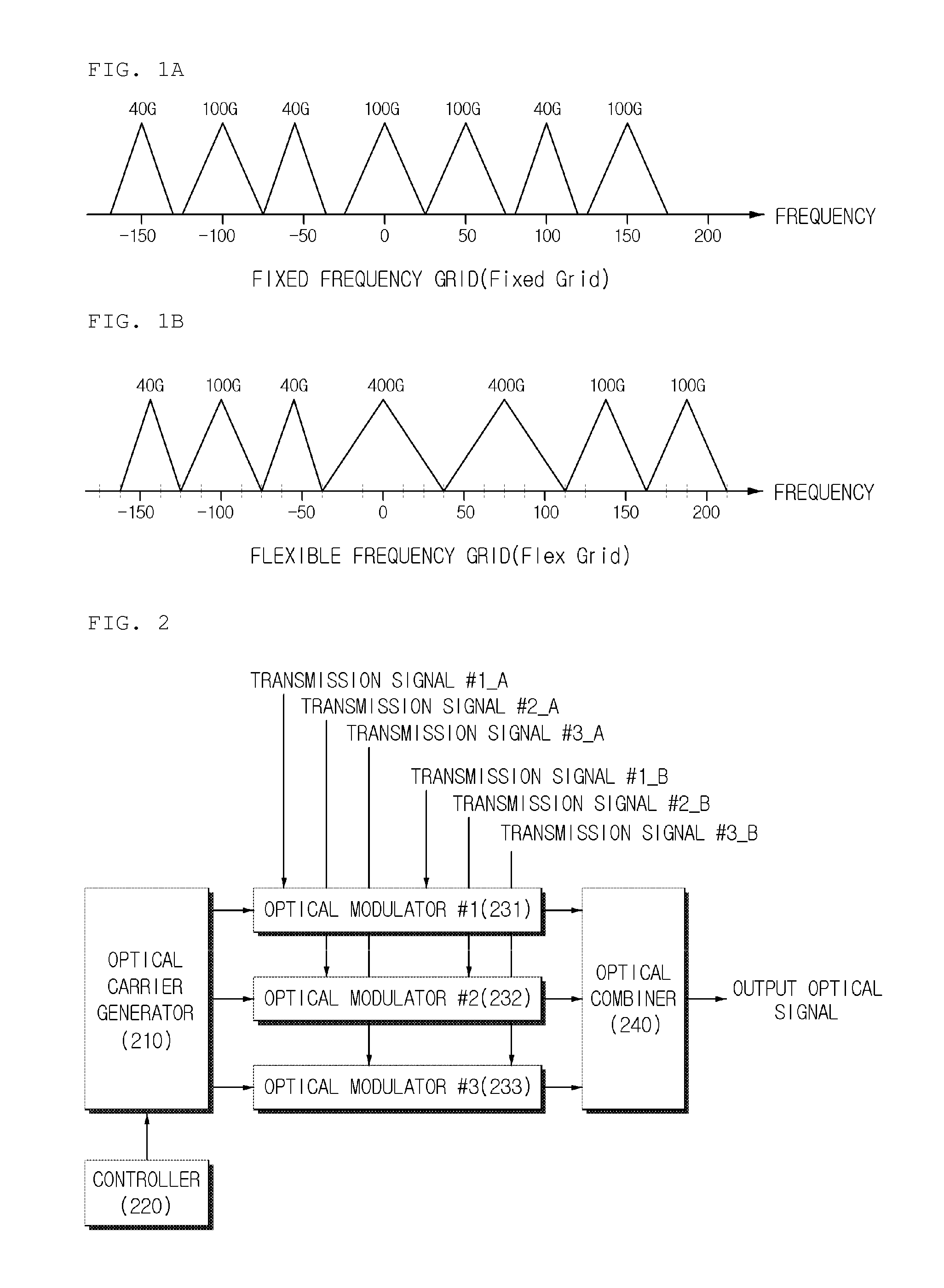
[0038]FIG. 2 illustrates an optical signal transmitting apparatus according to an exemplary embodiment of the present invention. The optical signal transmitting apparatus according to the present exemplary embodiment includes an...


PUM


Abstract

Disclosed is an optical signal transmitting apparatus including: an optical carrier generator configured to generate a plurality of optical carriers and outputs the optical carriers to optical modulators corresponding to the optical carriers, respectively; a plurality of optical modulators configured to modulate the optical carriers, respectively, according to an input signal; and an optical combiner configured to couple a plurality of optical signals from the plurality of optical modulators.

Description

CROSS-REFERENCE TO RELATED APPLICATIONS[0001]This application claims priority to and the benefit of Korean Patent Application No. 10-2011-0141237 filed in the Korean Intellectual Property Office on Dec. 23, 2011, the entire contents of which are incorporated herein by reference.TECHNICAL FIELD[0002]The present invention relates to an optical signal transmitting apparatus and an optical signal receiving apparatus, and more particularly, to a multicarrier based optical signal transmitting apparatus which transmits high-speed signals by using several optical carriers, and a multicarrier based optical signal receiving apparatus.BACKGROUND ART[0003]In recent years, the amounts of traffics generated in networks are continuously increasing due to popularization of smart phones, high-resolution TVs and the like, and transmission speeds for channels of optical transmission networks are expected to increase up to 400 Gb / s or 1 Tb / s, exceeding 100 Gb / s. A non-return-to-zero (NRZ) method where ...

Claims


Application Information

Patent Timeline
Patent Type & Authority Patents(United States)
IPC IPC(8): H04B10/00H04J14/02
CPCH04J14/026H04J14/0224H04B10/50H04B10/60
Inventor CHUNG, HWAN SEOKCHANG, SUN HYOK
Owner ELECTRONICS & TELECOMM RES INST
Why Eureka
Try Eureka