Reflective optical source device

a technology of optical source and reflector, which is applied in the direction of optical elements, semiconductor lasers, instruments, etc., can solve the problems of low establishment cost of optical source devices, low chirp property in a wide wavelength band, and difficulty in obtaining uniform extinction ratios

Inactive Publication Date: 2016-10-25
ELECTRONICS & TELECOMM RES INST
View PDF7 Cites 3 Cited by
  • Summary
  • Abstract
  • Description
  • Claims
  • Application Information

AI Technical Summary

Benefits of technology

[0022]According to the exemplary embodiment of the present invention, the optical source device controls a temperature of a local region by integrating the heater to each of the semiconductor optical amplifier and the electro absorption modulator, thereby adjust a gain characteristic of the semiconductor optical amplifier, and adjusts the band gap of the electro absorption modulator, thereby achieving a high-speed operation and a long-distance transmission for an input optical signal power in a wide wavelength band and a wide range.

Problems solved by technology

Further, the injection type broadband optical source is relatively easy to implement a system, and establishment cost thereof is low, compared to the wavelength tunable laser.
Unlikely, the modulation characteristics of EAM is strongly depends on the wavelength difference between the band gap of EAM and the operation wavelength, so that it is difficult to obtain a uniform extinction ratio, low optical loss, and a low chirp property in a wide wavelength band.
Accordingly, the EAM has a characteristic in that an operation wavelength band is relatively narrower than that of the SOA, so that the REAM-SOA has difficulty in efficiently amplifying and modulating a high-speed optical signal in a wide operation wavelength band.
In order to solve the disadvantage, an optical device having the same function may be manufactured by integrating a Mach-Zehnder Interferometer (MZI), but the optical device integrated with the MZI has a complex process, a low yield, and a relatively long length compared to the EAM.
Accordingly, the optical device integrated with the MZI is not appropriate as a small and low cost broadband optical source.
However, in the SOA, a noise problem is generated in a low input power, and a signal distortion is generated by gain saturation in a high input power, so that the SOA has an input power dynamic range in which an optical signal can transmit with low transmission power penalty.

Method used


Image

  • Reflective optical source device
  • Reflective optical source device
  • Reflective optical source device

Examples


Embodiment Construction

[0031]Hereinafter, exemplary embodiments according to the present invention will be described in detail with reference to the accompanying drawings. In the description below, it should be noted that only parts necessary for understanding operations according to various exemplary embodiments of the present invention will be described, and descriptions of other parts may be omitted so as to avoid unnecessarily obscuring the subject matter of the present invention.

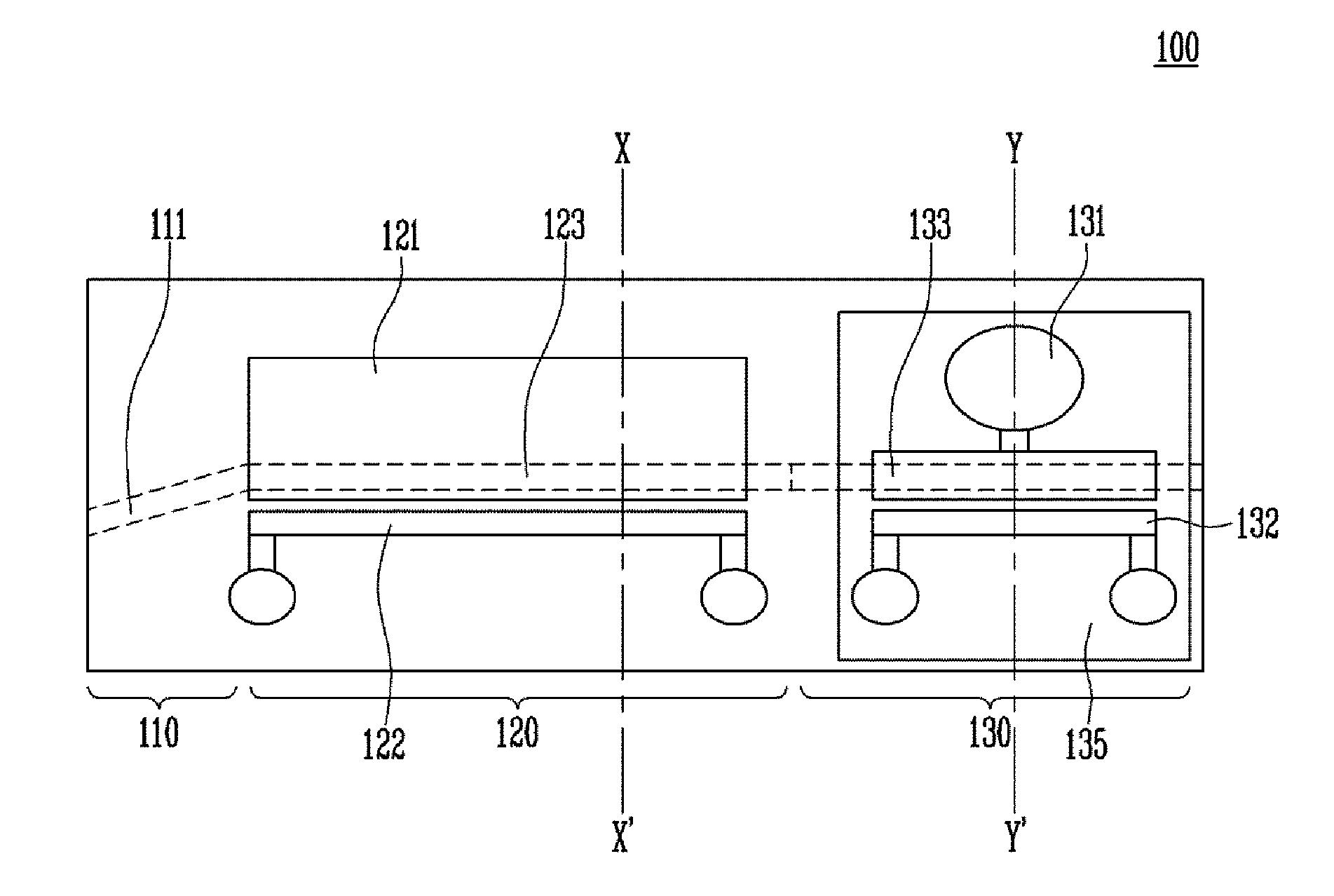
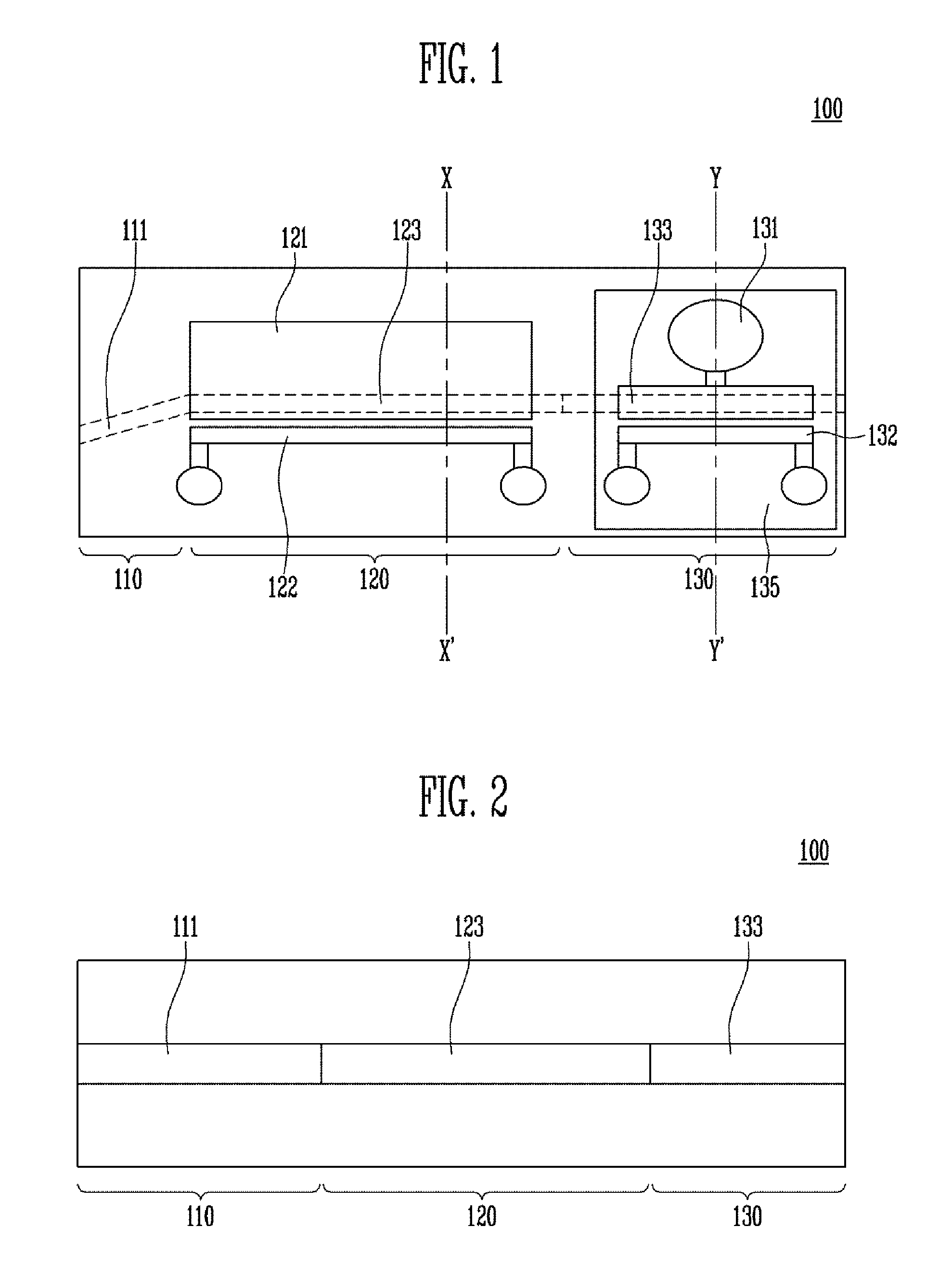
[0032]The present invention provides an optical source device capable of modulating and amplifying an optical signal of about 10 Gbps or more and long-distance transmitting the modulated and amplified optical signal without being dependent on a wavelength in an optical communication network, for example, a Wavelength Division Multiplexing-Passive Optical Network (WDM-PON). Here, the optical source device uses an injection type broadband optical source, so that it is not necessary to control a wavelength of an optical source, ...


PUM

PropertyMeasurementUnit
thicknessaaaaaaaaaa
reflectanceaaaaaaaaaa

Abstract

Disclosed is an optical source device. The optical source device includes: a mode converter configured to be optically coupled with an optical fiber; a semiconductor optical amplifier coupled with the mode converter, and configured to amplify an optical signal input through the optical fiber; and an electro absorption modulator coupled to the optical amplifier, and configured to modulate the amplified optical signal and output the modulated optical signal, in which each of the semiconductor optical amplifier and the optical absorption modulator includes a heater.

Description

CROSS-REFERENCE TO RELATED APPLICATION[0001]This application is based on and claims priority from Korean Patent Application No. 10-2014-0017899, filed on Feb. 17, 2014, with the Korean Intellectual Property Office, the disclosure of which is incorporated herein in its entirety by reference.BACKGROUND[0002]1. Field[0003]The present invention relates to an optical signal processing system, and more particularly, to an optical source device capable of high-speed modulating and long-distance transmitting an input optical signal.[0004]2. Discussion of Related Art[0005]In general, an injection type broadband optical source does not require a control of a wavelength of an optical source of an optical transmitter, and a manufacturing process of the optical source is simple, compared to a Wavelength Division Multiplexing-Passive Optical Network (WDM-PON) method using a non-injection type optical source, such as a wavelength tunable laser. Further, the injection type broadband optical source ...

Claims


Application Information

Patent Timeline
Patent Type & Authority Patents(United States)
IPC IPC(8): G02F1/03G02F1/07G02B1/113G02B6/14G02F1/01G02F1/017G02F1/015H01S5/50H01S5/026
CPCG02B1/113G02B6/14G02F1/0102G02F1/01708G02F2001/0157H01S5/0261H01S5/0265H01S5/50G02B6/12004G02B2006/12078G02B2006/12142G02B2006/12152G02F1/0157
Inventor LEE, DONG HUNJEONG, JONG SOOLKIM, KI SOOKIM, HYUN SOOPARK, MI RANKWON, O KYUN
Owner ELECTRONICS & TELECOMM RES INST
Why Eureka
Try Eureka