Image transmission apparatus and image reception apparatus

a transmission apparatus and image technology, applied in the field of image transmission apparatus and image reception apparatus, can solve the problems of limited positional relationship between a surgeon, a subject, and the display device, and achieve the effect of reliability acquiring high-definition still image data taking time for communication

Active Publication Date: 2012-05-31
OLYMPUS CORP
View PDF9 Cites 10 Cited by
  • Summary
  • Abstract
  • Description
  • Claims
  • Application Information

AI Technical Summary

Benefits of technology

[0016]According to the present invention, the image transmission terminal and the image reception terminal disconnect the communication after the im

Problems solved by technology

Thereby, a positional relationship among a surgeon, a subject, and the display device is limited due to the cable.
However, if a still image of the inside of the coelom is acquired by image pickup, it is difficult for a surgeon, who is manipulating t

Method used


Image

  • Image transmission apparatus and image reception apparatus
  • Image transmission apparatus and image reception apparatus
  • Image transmission apparatus and image reception apparatus

Examples


first preferred embodiment

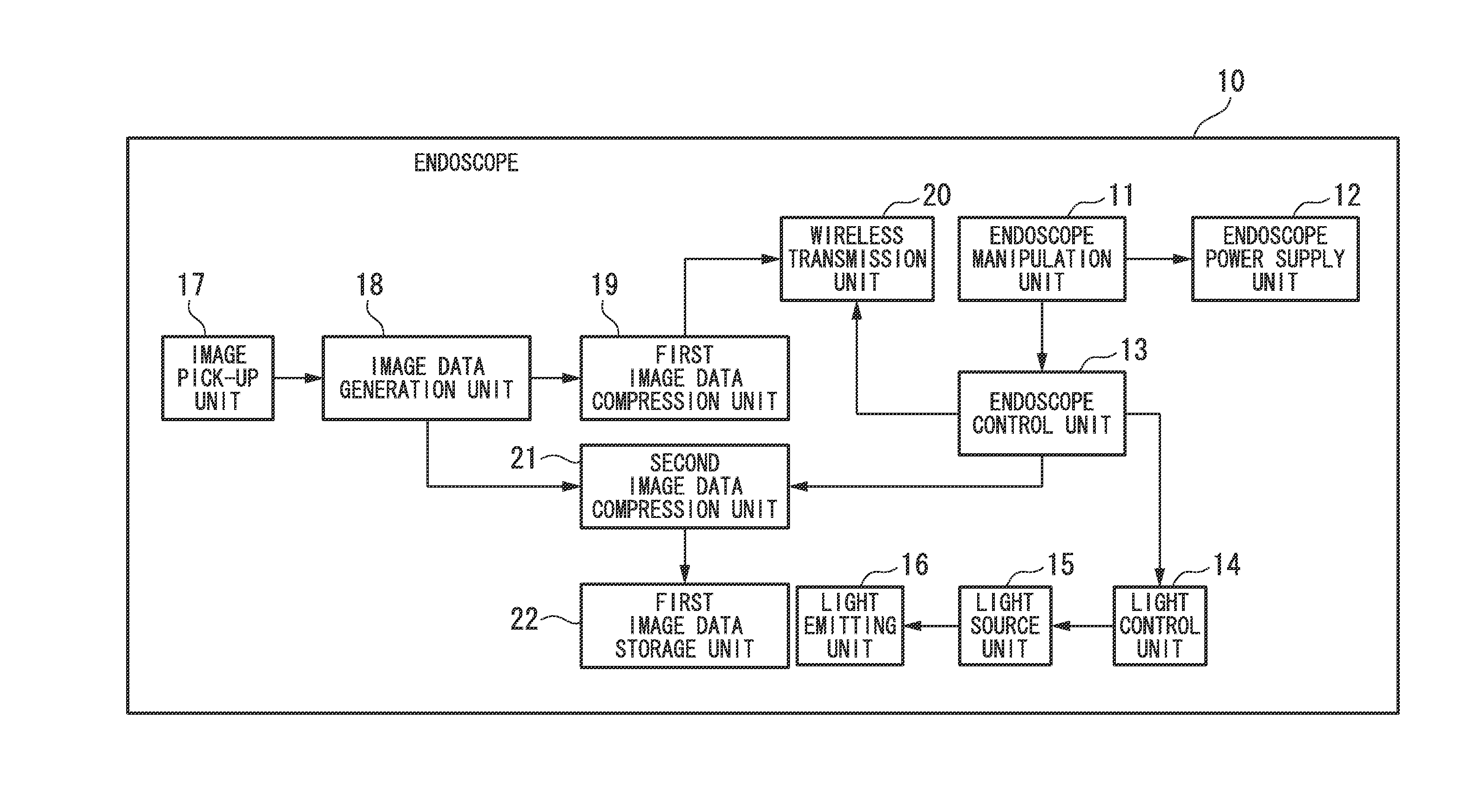
[0032]Next, a preferred embodiment of the present invention will be described in detail with reference to the accompanying drawings. FIG. 1 is a block diagram illustrating an endoscope (image transmitting terminal) in accordance with the first preferred embodiment of the present. In FIG. 1, an endoscope 10 includes an endoscope manipulation unit 11, an endoscope power supply unit 12, an endoscope control unit 13, a light control unit14, a light source unit 15, a light emitting unit 16, an image pickup unit 17, an image data generation unit 18, a first image data compression unit 19, a wireless transmission unit 20, a second image data compression unit 21, and a first image data storage unit 22.

[0033]The endoscope manipulation unit 11 receives a manipulation input from a surgeon (user), and outputs a manipulation signal to the endoscope control unit 13 and the endoscope power supply unit 12. The endoscope power supply unit 12 receives a communication connection instruction as the man...

second preferred embodiment

[0061]Next, a second preferred embodiment of the present invention will be described. FIG. 5 is a block diagram illustrating an endoscope in accordance with the second preferred embodiment of the present invention. In FIG. 5, an endoscope 40 includes an endoscope manipulation unit 41, an endoscope power supply unit 42, an endoscope control unit 43, a light control unit 44, a light source unit 45, a light emitting unit 46, an image pickup unit 47, an image data generation unit 48, a first image data compression unit 49, a first wireless transmission unit 50, a second image data compression unit 51, a third image data storage unit 52, and a second wireless transmission unit 53.

[0062]The endoscope manipulation unit 41 performs the same operation as the endoscope manipulation unit 11 in FIG. 1. The endoscope power supply unit 42 performs the same operation as the endoscope power supply unit 12 in FIG. 1. The endoscope control unit 43 performs the same operation as the endoscope control ...

third preferred embodiment

[0102]Next, a third preferred embodiment of the present invention will be described. FIG. 11 is a block diagram illustrating an endoscope in accordance with the third preferred embodiment of the present invention. In FIG. 11, an endoscope 80 (image transmission apparatus) includes an endoscope manipulation unit 81, an endoscope power supply unit 82 (power supply unit), an endoscope control unit 83 (control unit), a light control unit 84, a light source unit 85, a light emitting unit 86, an image pickup unit 87, an image data generation unit 88, a first image data compression unit 89, a first wireless transmission unit 90, a second image data compression unit 91, an image data storage unit 92, a second wireless transmission unit 93, and a wireless reception unit 94.

[0103]In FIG. 11, the endoscope manipulation unit 81, the light control unit 84, the light source unit 85, the light emitting unit 86, the image pickup unit 87, the image data generation unit 88, the first image data compr...


PUM


Abstract

An image transmission apparatus may include a transmission unit that transmits a moving image compressed by lossy compression as first image data to an external apparatus through wireless communication, the transmission unit transmitting image data corresponding to one image in the moving image as second image data, the second image data being image data compressed at a lower compression rate than the lossy compression or not compressed, an instructing unit that outputs a disconnection signal to disconnect the wireless communication in response to an external manipulation, and a control unit that receives the disconnection signal from the instructing unit, the control unit controlling to disconnect the wireless communication in the transmission unit after the transmission of the second image data in the transmission unit has been completed.

Description

TECHNICAL FIELD[0001]The present invention relates to an image transmission apparatus and an image reception apparatus.[0002]Priority is claimed on Japanese Patent Application No. 2009-142117, filed Jun. 15, 2009, the content of which is incorporated herein by reference.BACKGROUND ART[0003]In recent years, as early detection and diagnostic accuracy for lesions using endoscope examination has been improved and various treatment tools included in an endoscope have been developed, further performance improvement of the endoscope is highly expected. However, image data of the inside of a coelom imaged by the endoscope is communicated to a display device, which is provided in a position away from the endoscope, via an image transmission cable (hereinafter referred to as cable). Thereby, a positional relationship among a surgeon, a subject, and the display device is limited due to the cable.[0004]An endoscope that overcomes the limitation of a positional relationship among a surgeon, a su...

Claims


Application Information

Patent Timeline
IPC IPC(8): H04N11/02A61B1/04H04N7/173H04N7/18H04N21/234H04N21/2743H04N21/426H04N21/442H04N21/61H04N21/65
CPCA61B1/00016A61B1/00036H04N7/183A61B5/7232
Inventor KAWASAKI, SHINYAHONDA, TAKEMITSU
Owner OLYMPUS CORP
Why Eureka
Try Eureka