Supercharge Your Innovation With Domain-Expert AI Agents!

Antenna Selection Method and Device

Inactive Publication Date: 2012-06-07
MEDIATEK INC
View PDF13 Cites 12 Cited by
  • Summary
  • Abstract
  • Description
  • Claims
  • Application Information

AI Technical Summary

Benefits of technology

[0009]The present invention discloses an antenna selection method, including utilizing each of a plurality of antennas to receive a plurality of transmission signals from a plurality of stations, respectively, to generate a plurality of reception signals; estimating a plurality of signal quality indicators corresponding to the plurality of stations according to the plurality of reception signals for each of the plurality of antennas, respectively; calculating a weighted sum of the plurality of corresponding signal quality indicators to generate a calculation result for each of the plurality of antennas; and selecting a receiving antenna from the plurality of antennas according to the corresponding calculation result of each of the plurality of antennas, respectively.
[0010]The present invention further discloses an antenna selection device for a wireless network system having a plurality of antennas, including a signal conversion unit, coupled to the plurality of antennas, for converting a plurality of transmission signals received by the plurality of antennas into a plurality of reception signals,

Problems solved by technology

Generally, in a wireless communication network, environmental effects cause wireless signals to suffer unknown phase shift and amplitude attenuation during transmission, resulting in interference in signals received by a receiving terminal and signal distortion, affecting signal transmission efficiency.
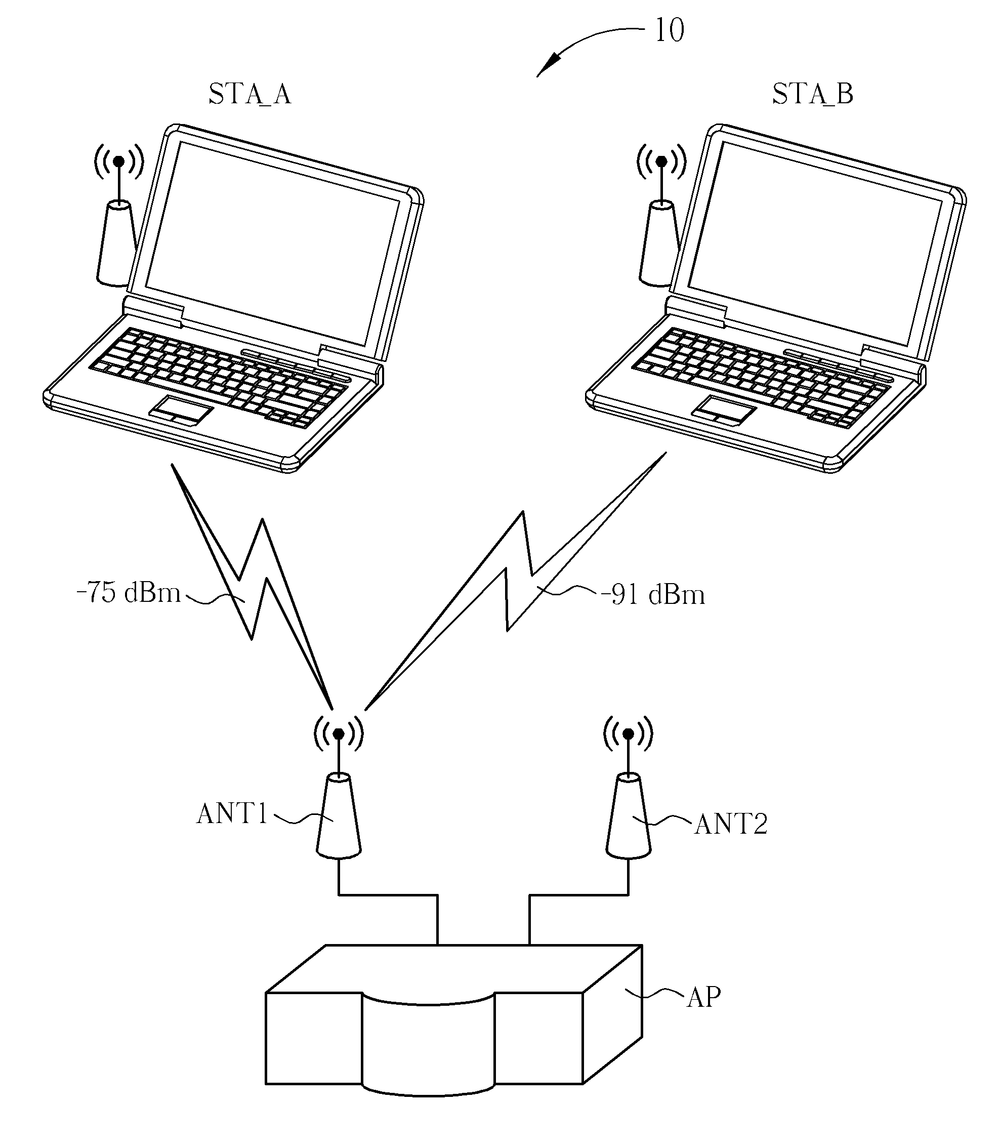
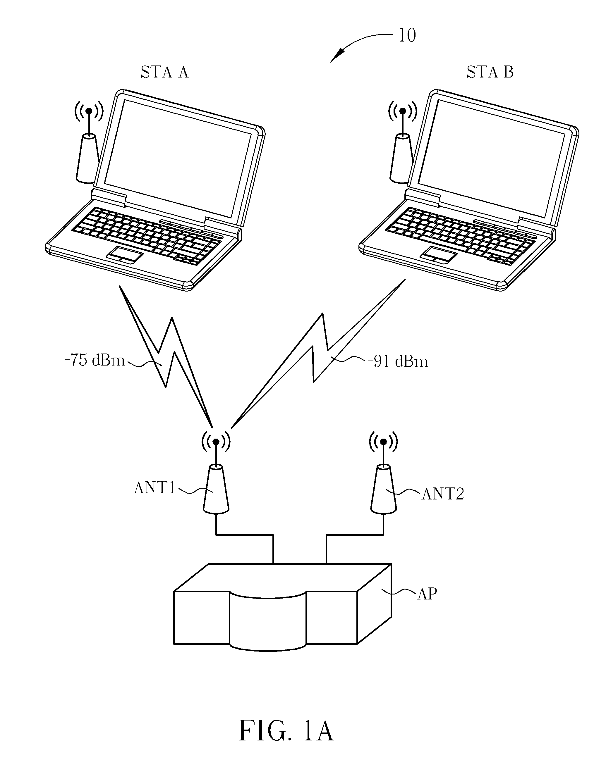
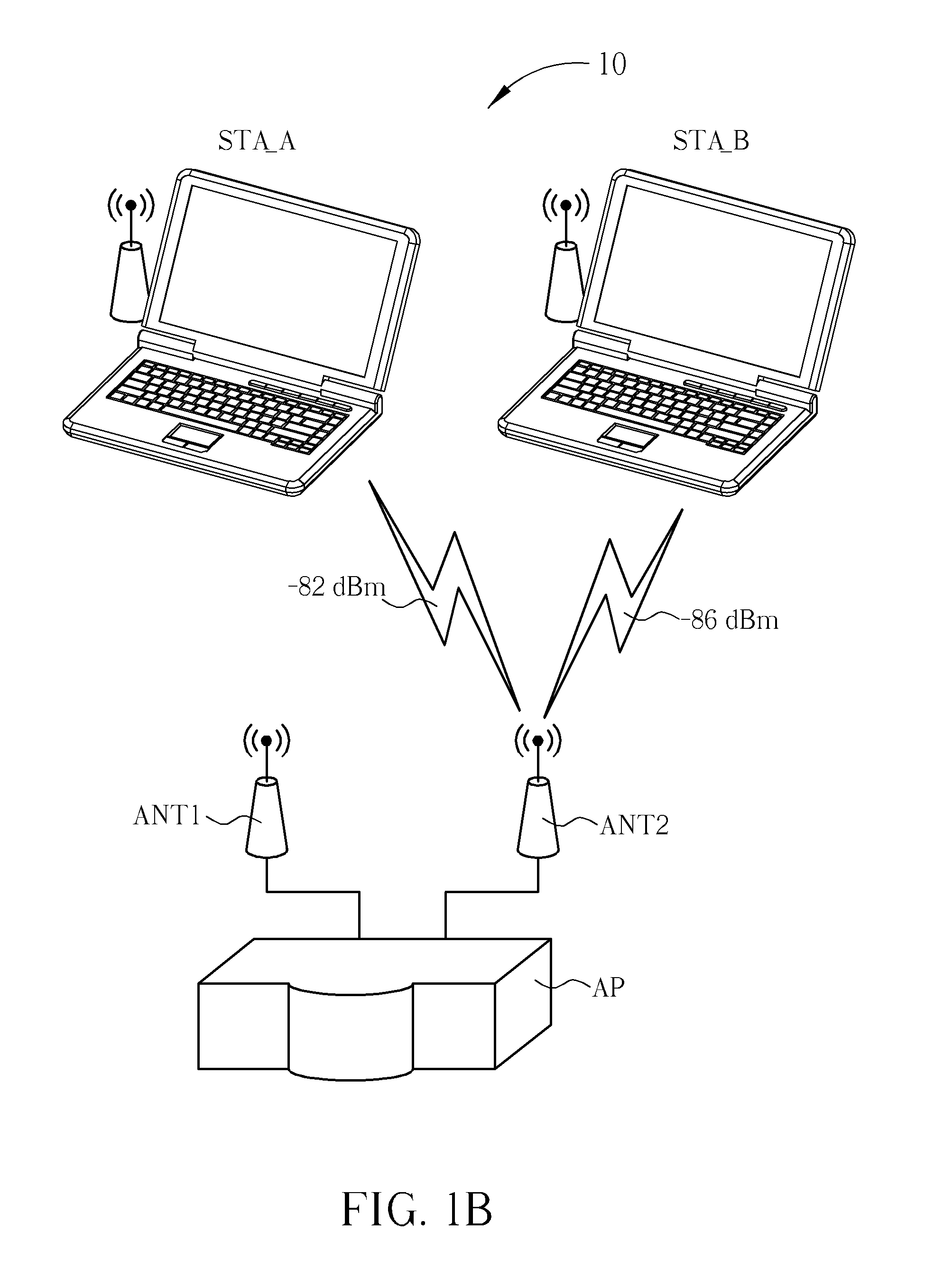
However, although the aforementioned antenna selection method ensures transmission and also a better connection quality between the user station having a higher RSSI value and a corresponding receiving antenna, the access point AP fails to cover as much range in the wireless network system as possible.
However, ultimately the antenna ANT2 is not selected for communication.
Simply put, though the above-mentioned conventional receiving antenna selection method ensures optimal connection quality between certain user stations and the receiving antenna, it precludes a transmission connection opportunity for other user stations, and thus reducing an overall signal transmission efficiency.
Since the prior art techniques are unable to determine whether or not a received signal is related to the corresponding access point when obtaining RSSI for receiving signals, the aforementioned unrelated signal strength information would easily be mistaken as basis for determination; as such, it is easy to mistakenly select an antenna with higher signal interference in an open network environment.
In short, unless placed in a “clean” wireless network environment, antenna switching selection would be easily interfered by other surrounding wireless devices unrelated to the corresponding access point.

Method used


Image

  • Antenna Selection Method and Device
  • Antenna Selection Method and Device
  • Antenna Selection Method and Device

Examples


Embodiment Construction

[0015]Please refer to FIG. 2, which is a schematic diagram of a wireless network system 20 according to an embodiment of the present invention. Preferably, the wireless network system 20 conforms to IEEE 802.11 wireless local area network (LAN) standards, but is not limited thereto. The wireless network system 20 includes user stations STA_A, STA_B, antennas ANT1, ANT2, an antenna selection device 200 and an access point AP. In the wireless network system 20, the user stations STA_A and STA_B may transmit and receive wireless signals to / from the access point AP via the antenna ANT1 or the antenna ANT2 to build communication transmission with the access point AP. To accommodate mobility and arbitrary connectivity characteristics of the wireless network system, the antenna selection device 200 selects a suitable receiving antenna from the antennas ANT1 and ANT2 every specific time interval, such that the user stations STA_A and STA_B may build high quality transmissions with the acces...


PUM


Abstract

An antenna selection method includes respectively utilizing each antenna of a plurality of antennas to receive a plurality of transmission signals from a plurality of stations to generate a plurality of reception signals, respectively estimating a plurality of signal quality indicators corresponding to the plurality of stations according to the plurality of reception signals for each of the plurality of antennas, calculating a weighted sum of the plurality of corresponding signal quality indicators to generate a calculation result for each of the plurality of antennas, and selecting a receiving antenna from the plurality of antennas according to the corresponding calculation result of each of the plurality of antennas.

Description

BACKGROUND OF THE INVENTION[0001]1. Field of the Invention[0002]The present invention relates to an antenna selection method and related device, and more particularly, to an antenna selection method capable of estimating wireless signal strength via weighted distribution and related device.[0003]2. Description of the Prior Art[0004]Advances in wireless network technologies, in addition to convenience and mobility of wireless networks, have led to an increasing amount of wireless communication network applications. Generally, in a wireless communication network, environmental effects cause wireless signals to suffer unknown phase shift and amplitude attenuation during transmission, resulting in interference in signals received by a receiving terminal and signal distortion, affecting signal transmission efficiency.[0005]Therefore, to enhance signal transmission efficiency, conventional techniques often utilize antenna diversity techniques to solve the above-mentioned issues. Generally...

Claims


Application Information

Patent Timeline
IPC IPC(8): H04W24/00
CPCH04B7/082
Inventor TSENG, KUO-WEICHEN, CHIEN-CHIA
Owner MEDIATEK INC
Features
  • R&D
  • Intellectual Property
  • Life Sciences
  • Materials
  • Tech Scout
  • Unparalleled Data Quality
  • Higher Quality Content
  • 60% Fewer Hallucinations
Learn More