Welding wire feeder with improved wire guide

Inactive Publication Date: 2012-06-21
ILLINOIS TOOL WORKS INC
View PDF10 Cites 5 Cited by
  • Summary
  • Abstract
  • Description
  • Claims
  • Application Information

AI Technical Summary

Benefits of technology

[0006]In another embodiment, a welding system includes a welding wire feeder including a wire spool, a pair of wire feed rolls configured to supply wire to a welding torch, and a wire guide adapted to guide wire from whatever angle the wire comes off the spool in the horizontal and vertical planes without damaging the outer surface of the wire. The wire guide may have a generally conical shape and include an oblong entrance end and an oblong exit end and a tapered inner wall. The wire guide funnels the wire from an angle tangent to the spool to the fixed angle required by the feed rolls without damaging the wire.

Problems solved by technology

Unfortunately, such an arrangement forces the wire into a fixed entry angle by sharply redirecting the wire as it enters the cylindrical guide.
This leads to deformation of the wire surface and causes shavings from the wire to detach, which can ultimately clog welding torch liners and tips.

Method used


Image

  • Welding wire feeder with improved wire guide
  • Welding wire feeder with improved wire guide
  • Welding wire feeder with improved wire guide

Examples


Embodiment Construction

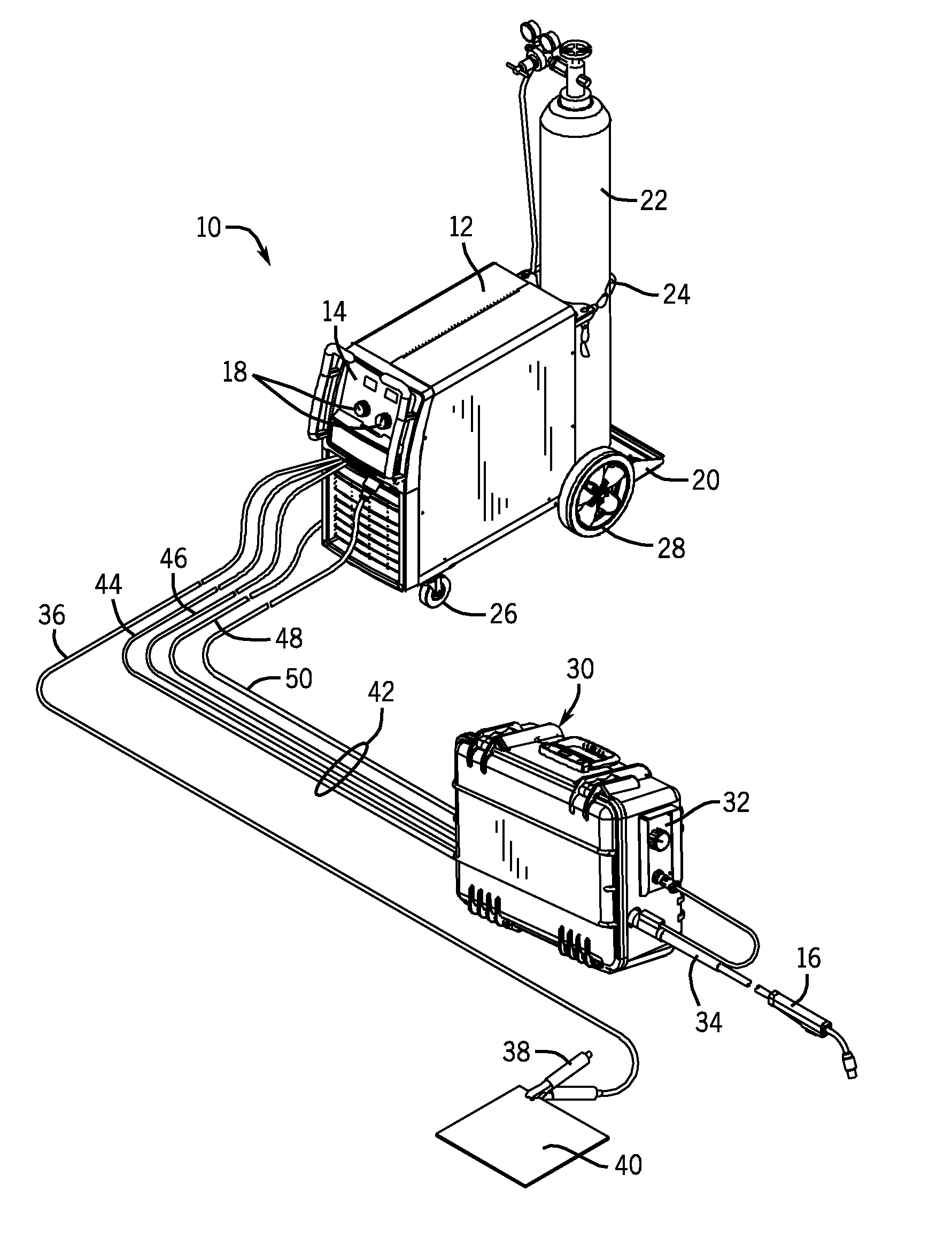
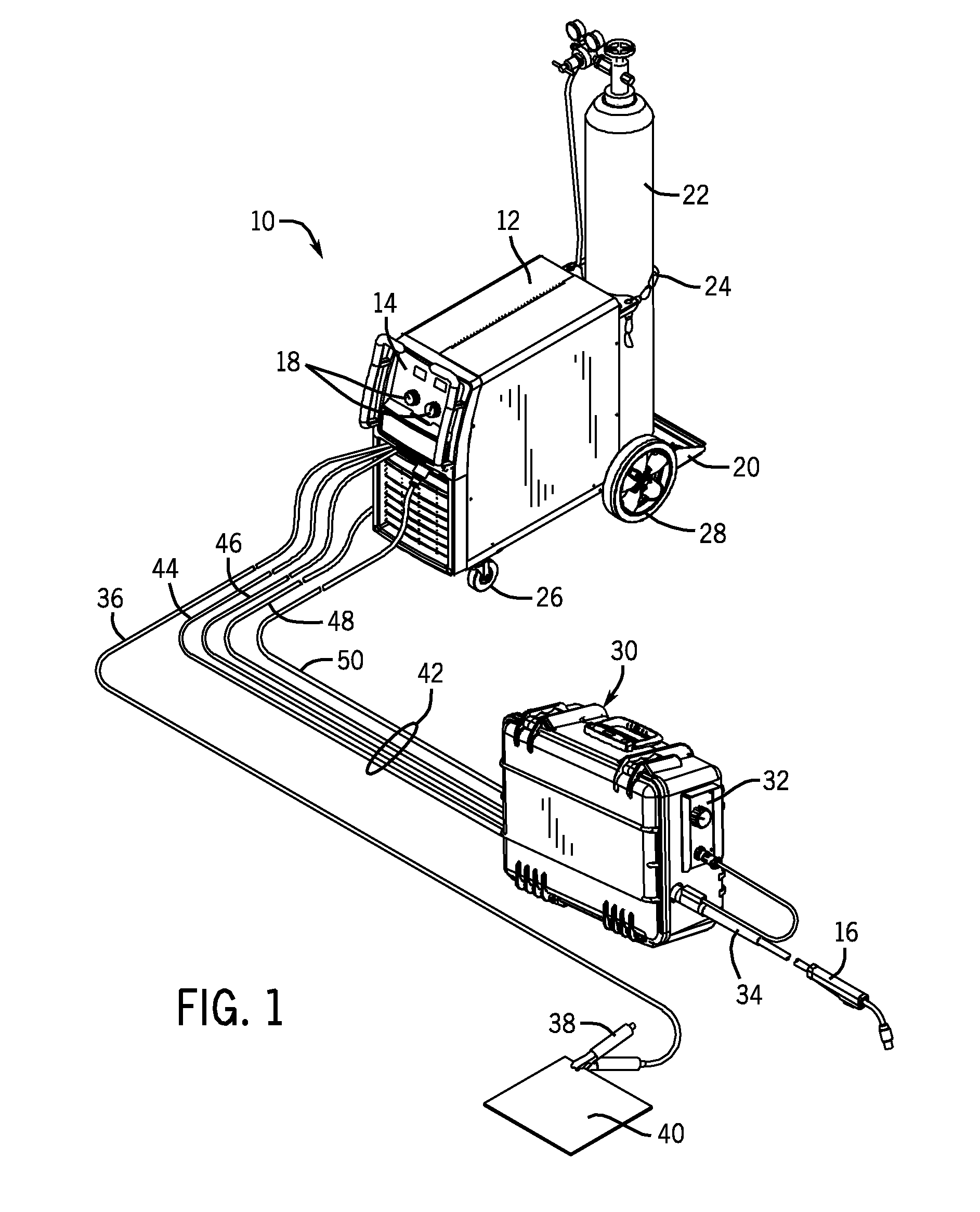
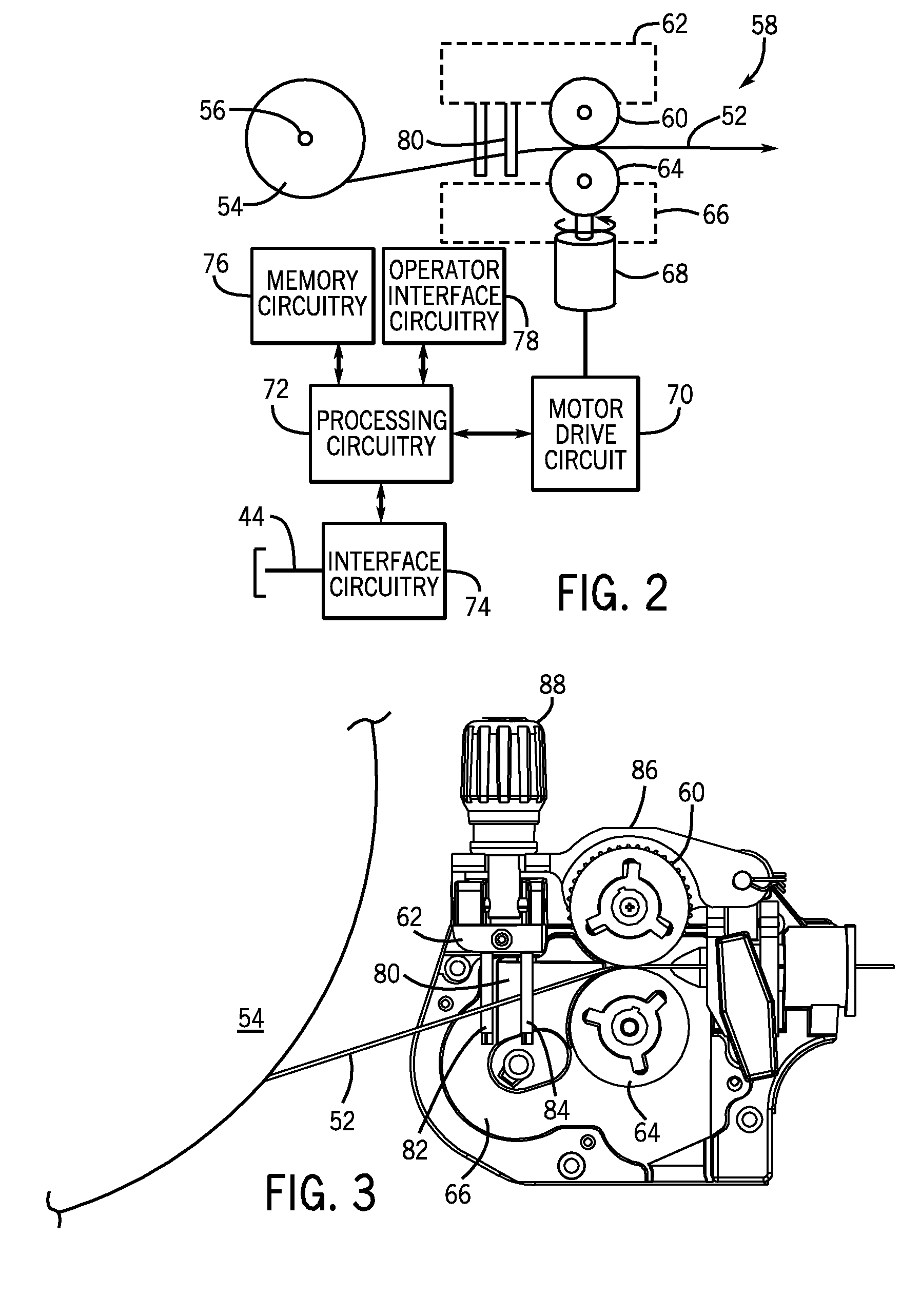
[0017]As described in detail below, embodiments of an improved wire guide for use in a welding wire feeder are provided. The wire guide is adapted to direct welding wire from a spool to the feed rolls of a wire drive assembly without causing damage to the outer surface of the wire. The wire guide may comprise an elongated slit, such as formed between two pins that direct wire coming off the spool at a range of angles in the vertical plane and in the horizontal plane. The two pins are attached vertically to the wire drive assembly, between the spool and the feed rolls. Welding wire may pass between the pins or make contact with the pins without damaging the outer surface of the wire because the angle of the wire is not sharply redirected. Still further, in certain embodiments, the wire guide may consist of a generally conical piece with an entrance end, an exit end, and a tapered inner wall. Welding wire is funneled through the conical guide to the feed rolls with a gradual redirecti...


PUM

PropertyMeasurementUnit
Dimensionaaaaaaaaaa

Abstract

A wire guide for use in a welding wire feeder is provided. The wire guide may consist of a pair of vertical pins mounted to a wire drive assembly to form a slit through which welding wire is guided toward a set of drive rolls. Another embodiment may consist of a generally conical piece with oblong entrance and exit ends mounted to the wire drive assembly.

Description

CROSS REFERENCE TO RELATED APPLICATIONS[0001]This application is a Non-Provisional patent application of U.S. Provisional Patent Application No. 61 / 423,837, entitled “Obround / Elliptical Guide”, filed Dec. 16, 2010 and of U.S. Provisional Patent Application No. 61 / 423,843, entitled “Inlet Guide Pins”, filed Dec. 16, 2010, which are herein incorporated by reference.BACKGROUND[0002]The invention relates generally to welding systems, and, more particularly, to a welding wire guide for use in a welding system.[0003]Welding is a process that has increasingly become ubiquitous in various industries and applications. While such processes may be automated in certain contexts, a large number of applications continue to exist for manual welding operations. Such welding operations rely on a variety of types of equipment to ensure the supply of welding consumables (e.g., wire feed, shielding gas, etc.) is provided to the weld in an appropriate amount at the desired time. For example, metal inert...

Claims


Application Information

Patent Timeline
IPC IPC(8): B23K9/00
CPCB23K9/125
Inventor CHRISTOPHER, MARK R.MATIASH, NICHOLAS A.
Owner ILLINOIS TOOL WORKS INC
Why Eureka
Try Eureka