Reinforced B-Pillar Assembly with Reinforced Rocker Joint

a technology of reinforced b-pillars and b-pillars, which is applied in the direction of roofs, transportation and packaging, vehicle arrangements, etc., can solve the problems of limited protection, significantly increasing vehicle weight, and challenging side impact collisions for vehicle safety engineers, and achieves the effect of improving side impact resistan

Active Publication Date: 2012-06-21
TESLA INC
View PDF32 Cites 23 Cited by
  • Summary
  • Abstract
  • Description
  • Claims
  • Application Information

AI Technical Summary

Benefits of technology

[0008]The present invention provides a reinforced B-pillar assembly that achieves improved side impact resistance by coupling the B-pillar assembly directly to an outer mounting surface of the rocker panel as well as to an extended brace that is attached to the upper and rear mounting surfaces of the rocker.

Problems solved by technology

Side impact collisions present a particularly challenging problem to vehicle safety engineers, both due to the relatively low position of the rocker panels on many small vehicles as well as the difficulty of implementing an impact resistant side structure while taking into account vehicle doors and doorways.
Although vehicle manufacturers use various structures and components to protect a vehicle's occupants during a side impact collision, typically these approaches provide only limited protection while significantly increasing vehicle weight.

Method used


Image

  • Reinforced B-Pillar Assembly with Reinforced Rocker Joint
  • Reinforced B-Pillar Assembly with Reinforced Rocker Joint
  • Reinforced B-Pillar Assembly with Reinforced Rocker Joint

Examples


Embodiment Construction

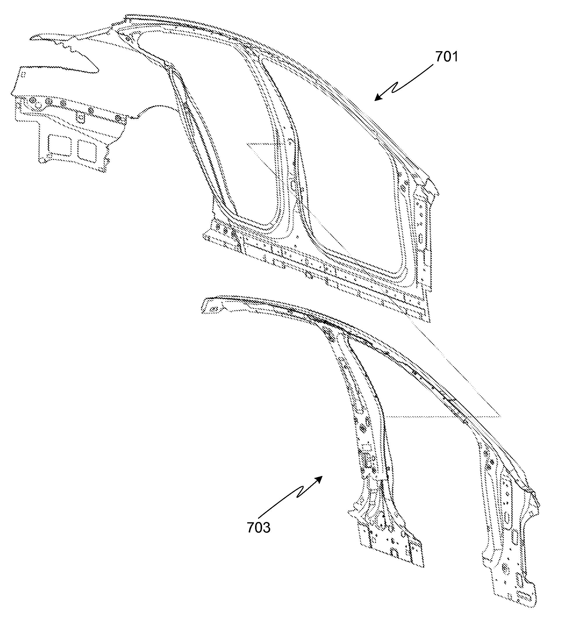
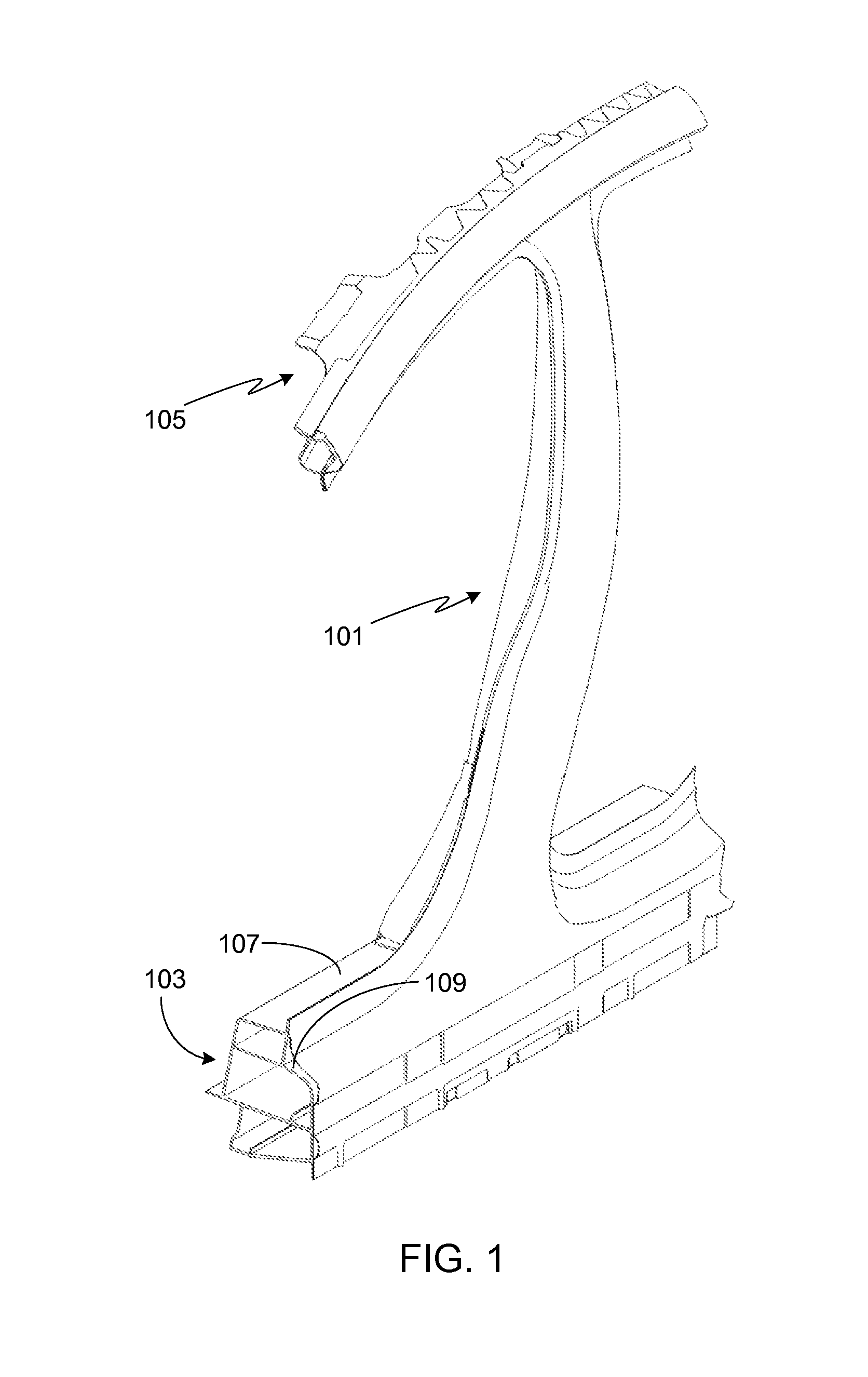
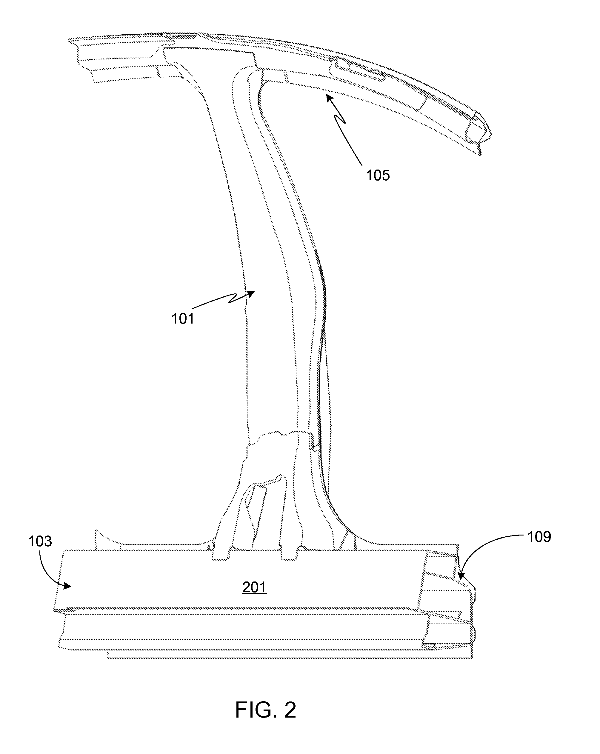
[0025]FIGS. 1 and 2 provide outside and inside perspective views, respectively, of a reinforced B-pillar assembly 101 attached to a rocker panel 103. Also visible in this figure is roofline structural assembly 105. FIG. 3 provides a cross-sectional view of the assemblies shown in FIGS. 1 and 2. As described in detail below and visible in FIG. 3, B-pillar assembly 101 includes at least one reinforcing member, thus increasing the strength of the pillar. Note that in order to improve the strength and rigidity of the overall assembly, the reinforcing member(s) is attached to rocker panel 103.

[0026]In order to distribute loads effectively to rocker 103, for example impact loads arising from a side impact collision, B-pillar assembly 101 is mechanically coupled to rocker 103 at multiple locations and on multiple surfaces. Specifically, B-pillar assembly 101 is coupled, directly or indirectly, to the rear surface 201, the upper surface 107, and the outer surface 109 of rocker 103. Rocker 1...


PUM


Abstract

A reinforced B-pillar assembly that achieves improved side impact resistance is provided in which the B-pillar assembly is mechanically coupled to an outer mounting surface of the rocker panel as well as to an extended brace that is attached to the upper and rear mounting surfaces of the rocker.

Description

CROSS-REFERENCE TO RELATED APPLICATION[0001]The present application is a continuation-in-part of U.S. patent application Ser. No. 13 / 308,206, filed 30 Nov. 2011, and claims benefit of the filing date of U.S. Provisional Patent Application Serial No. 61 / 424,900, filed 20 Dec. 2010, the disclosures of which are incorporated herein by reference for any and all purposes.FIELD OF THE INVENTION[0002]The present invention relates generally to vehicle structures and, more particularly, to an assembly comprising a rocker panel and a B-pillar.BACKGROUND OF THE INVENTION[0003]Modern vehicles use a variety of structures to protect the vehicle's occupants during a crash. Some of these structures are used to control the transmission of the crash energy to the passenger compartment while other structures, such as seat belts, head restraints, and air bags, are intended to restrain passenger movement during a crash, thereby preventing the passengers from hurting themselves as their bodies react to t...

Claims


Application Information

Patent Timeline
Patent Type & Authority Applications(United States)
IPC IPC(8): B62D25/04
CPCB62D25/04B62D25/025
Inventor RAWLINSON, PETER DOREBALDWIN, MICHAEL JOHNGADHIYA, HITENDRA LAXMIDAS
Owner TESLA INC
Why Eureka
Try Eureka